32
|
EN / SunMaster CS15TL RP / CS20TL RP / CS30TL RP
10.4 REACTIVE POWER EXPLANATION
A growing share of power coming from PV installations results
in a demand to keep the utility grid stable. Reactive power is an
inverter function which helps to stabilize the utility grid. It
enables adaptation of the power factor to reduce output power
when there is more supply than demand.
SunMaster CS inverters can generate Reactive power as
required by the VDE-AR-N 4105 regulations in Germany, which
will be introduced 1 September 2011. These regulations state
the following reactive power requirements:
Installation size Power factor
<3.68 kVA 1.00
3.68-13.8 kVA 0.95
>13.8 kVA 0.90
A power factor of 0.9 means the power fed back is reduced by
10%. In other words: there is 90% active (useful) power and
10% reactive (useless) power. In this case, a 30 kVA inverter
feeds 27 kW back into the grid.
Control for the reactive output can be adjusted to meet local
demands. To calculate the effect of reactive power on the
sizing of the installation, please download Mastervolts system
calculator SysCalc which is available for free on
www.mastervoltsolar.com. SysCalc takes into account the
effects of reactive power on cable losses. Mastervolt inverters,
if set to German country settings, will select default reactive
power settings. For adjustment of these settings, refer to
chapter 8.
10.5 REACTIVE POWER MANAGEMENT
Reactive power is needed in some installations to support
the local grid quality. A default configuration is programmed
for each installation country that is compliant to the applica-
ble national grid codes. In some cases, the local network
operator (DNO) may require to adjust the inverter settings.
The SunMaster CS supports four different control laws, out
of which one can be selected.
If the inverter is operating at an output power
below 20% of its nominal rating, the Reactive
Power output may deviate from the provided
settings. This is normal behavior for the
CS inverter.
The inverter can be set up to reduce the reactive power in
four different ways:
1. Cos phi – P
2. Q – U
3. Constant cos-phi
4. Constant Q
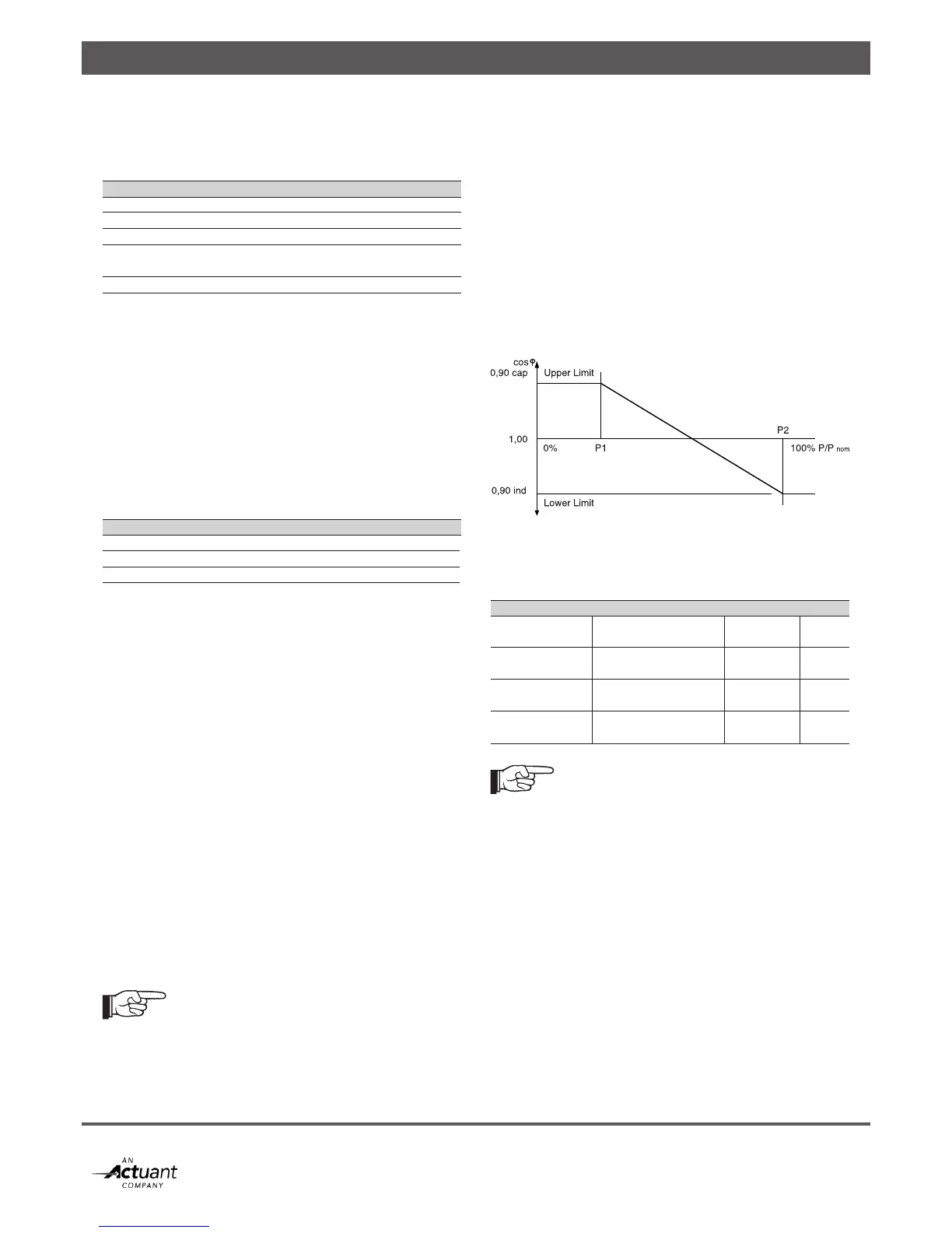
10.5.1 Power dependent power factor control
This control law (cos phi – P control) sets the phase angle
between voltage and current as a function of the inverter
output power. It is the default control loop selected for
operation in Germany. Figure 10-8 shows an example
demonstrating the available parameters.
Figure 10-8: Cos phi – P Control
The user (installer) can provide 4 independent setpoints:
Name Range Resolution Default
cos phi P1 0,90 ind -> 0,90 cap* 0,01 1,00
(Upper Limit)
cos phi P2 0,90 ind -> 0,90 cap* 0,01 0,95 ind
(Lower Limit)
Power Setpoint 1 0% -> 100% P/ Pnom 1% 50%
(P1)
Power Setpoint 2 0% -> 100% P/ Pnom 1% 100%
(P2)
cap = Capacitive generator
(i.e. over-excited generator, current lags voltage)
ind = Inductive generator
(i.e. under-excited generator, current leads voltage)
P2 cannot be set to a value equal to or below P1 (P1 < P2);
The Upper Limit cannot be set to a value below the Lower
Limit.
will increase its output power after the frequency has
recovered, or after a grid fault has been cleared.
4 independent setpoints are available:
Name Range Resolution Default
fstart 50 – 55 Hz / 60 – 65 Hz 0,01 Hz 50,20 Hz
frecover 50 – 55 Hz / 60 – 65 Hz 0,01 Hz 50,05 Hz
Gradient 0% _ 100% P/Pm/Hz 1% 40%
Ramp-Up 0% _ 6000%
P/Prated/min 10% 10%
Mode VDE / BDEW VDE
fstart can only be set to a value higher than fhigh,off (fhigh,off > fstart)