|
11
EN / SunMaster CS15TL RP / CS20TL RP / CS30TL RP
4.3.1 Recommended cabling
All devices within the PV installation (panels, wiring, terminal
blocks, fuse holders, fuses, switches, etc.) must be rated for
the applicable maximum voltage and current ratings.
Use double isolated DC cabling for all connections.
A sufficiently large copper cross section will help reducing
the cable losses.
Current 10ADC 20 ADC 30ADC
Length
<10 m 2.5 mm
2
4.0 mm
2
6.0 mm
2
10-20 m 4.0 mm
2
6.0 mm
2
10 mm
2
*
>20 m >4.0 mm
2
>6.0 mm
2
* >10 mm
2
*
*Cable adapter may be necessary for cross sections >6.0 mm
2
4.3.2 DC Connectors and switch
The SunMaster CS inverters use MC4 compatible DC
connectors with a 4 mm pin diameter.
Do not reverse the polarity of the PV
connections. The inverter will be permanently
damaged, and large short-circuit currents
may occur.
For safety reasons, the use of a suitable DC switch between
the PV modules and the inverter is recommended.
Depending on locally applicable regulations, such a switch
may be mandatory.
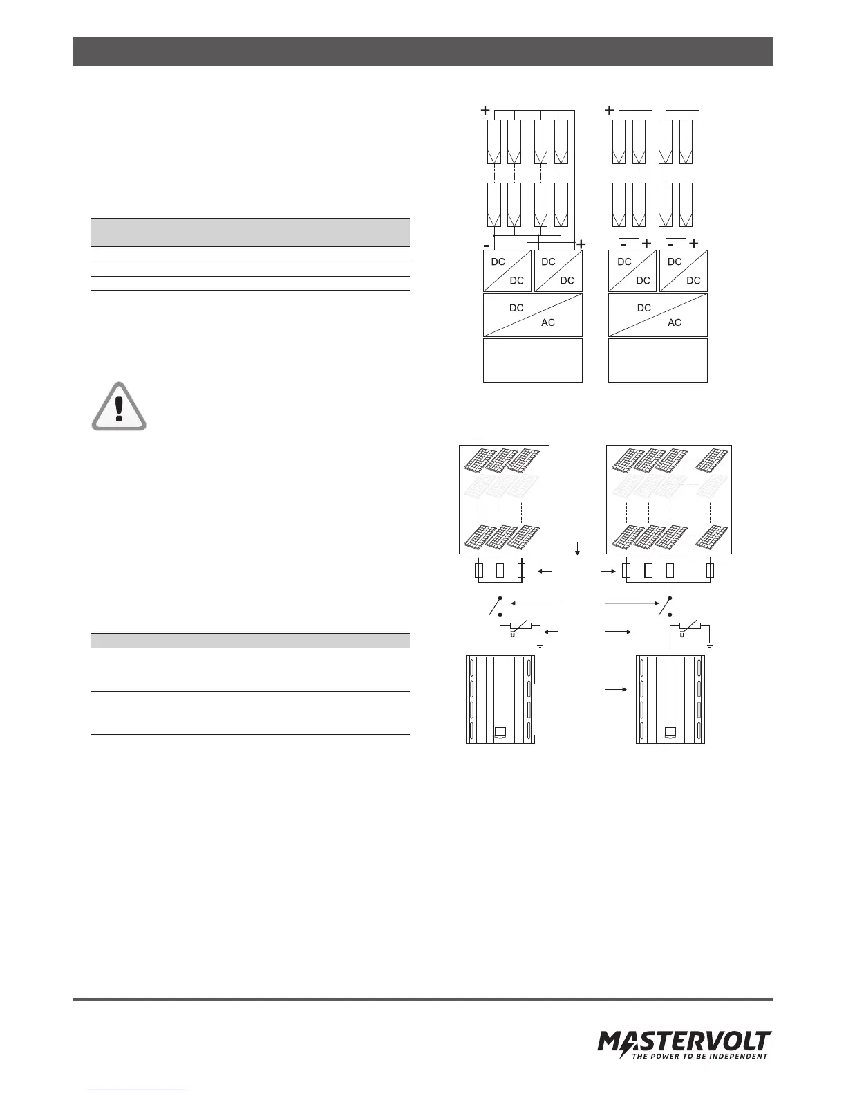
4.3.3 Parallel or independent operation
The SunMaster CS has two independently controlled inputs,
labelled “Input 1” and “Input 2”. These inputs can be used as
separate inputs or they can be connected in parallel depend-
ing on the PV installation. The inverter will automatically detect
if the inputs have been paralleled. Make sure to divide the PV
power over the two inputs as equally as possible.
Parallel operation Independent operation
For uneven number of Per input different array
strings in the array. configuration or orientation
possible.
Required when applying Reduce losses in case of local
functional grounding. shadowing.
Refer to chapter 11.
To accommodate more than 1 PV string on each input, a DC
combiner box such as StringMaster should be used. Refer to
the StringMaster manual for specific installation instructions.
When more than three strings are paralleled in an array, they
must be fused. Use only DC rated fuses with appropriate
voltage and current ratings.
To avoid excessive losses, always make sure the string
voltages are equal to each other before paralleling them.
Never use different string lengths or different module types
in the same array.
Figure 4-2: Parallel and independent operation
Figure 4-3: Functional scheme StringMaster
4.4 SOLAR ARRAY CAPACITANCE
Every solar panel has a small parasitic (virtual) capacitance
between the photo-sensitive material and the external
structure. In the PV array all these capacitances add up to
one larger (virtual) capacitance.
If this capacitance is too large, it causes a high leakage
current to flow from the main electrical path to the external
structure. Such currents can be dangerous to humans and
may further degrade the performance of the installation.