|
17
EN / SunMaster CS15TL RP / CS20TL RP / CS30TL RP
7 COMMUNICATION
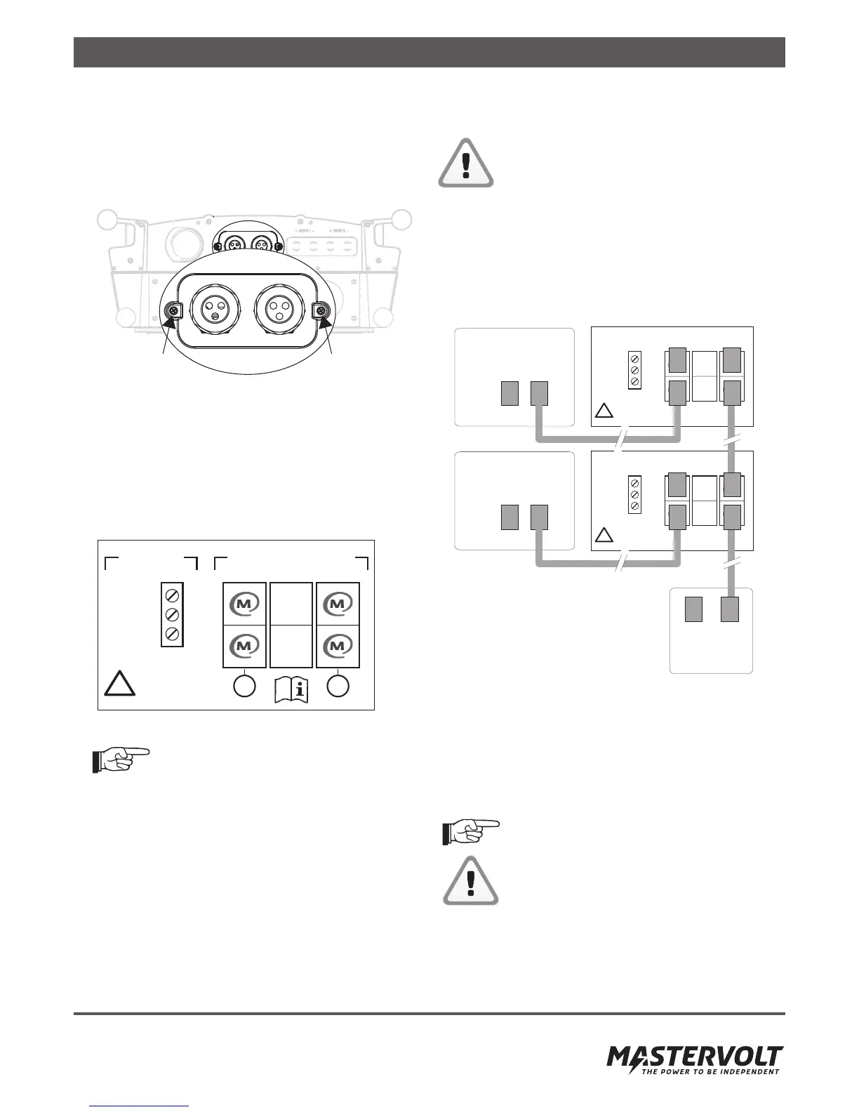
7.1 COMMUNICATION MODULE
The CS inverter is equipped with a detachable communication
module (drawer) for inserting the MasterBus and RS485 plugs.
It also facilitates mounting the alarm wiring.
Figure 7-1: Communication module
Install the communication wiring, see the steps below:
• Loosen the Phillips screws at both sides of the front plate
(see figure 7-1).
• Pull out the module, taking care not to damage the
connectors and components.
• Release glands and remove plugs where applicable.
• Insert the connectors and mount the alarm wiring.
See the label in figure 7-2 for more information.
Figure 7-2: Communication label
MasterBus connectors are similar to RS485
connectors! Wrong installation causes
communication failure.
7.2 MASTERBUS NETWORK
All devices that are suitable for MasterBus are marked by the
MasterBus symbol.
MasterBus is a fully decentralized data network for
communication between the different Mastervolt system
devices. The communication network is based on CAN-bus
which has proven a reliable bus-system. New devices can be
added to the existing network by just extending the network.
This gives the MasterBus network a high degree of exibility
for extended system configuration. Mastervolt also offers
several interfaces, making even non-MasterBus devices
suitable to operate in the MasterBus network.
CAUTION:
Never connect a non-MasterBus device to the
MasterBus network directly! This will void
warranty of all MasterBus devices connected.
7.3 MASTERBUS CONNECTORS
The CS inverter is equipped with 2 x 2 MasterBus connec-
tors (A and B) to install two MasterBus networks. Network A
is reserved for the string box or a transformer
connected to the CS inverter. The other network (B) is
reserved for communication and updating the inverter.
Figure 7-3: MasterBus network example
Proceed as follows to remount the communication module:
• Close any unused holes in the glands, using the
premounted caps.
• Insert communication module, using the guidance rails.
• Fix the Phillips screws at both sides of the front plate
(see figure 7-1).
For MasterBus connection of the CS-IT20
isolation transformer, refer to section 6.5.3.
Install the communication cables separated
from the AC and DC cables to prevent
communication loss caused by interference!
7.3.1 How to set up a communication network
Every device that is suitable for the RS 485 and MasterBus
network is equipped with two data ports. When two or more
devices are connected using these ports, together they form
a local data network.
NO
NC
COM
COMMUNICATION
A
Max 30V/1A
ALARM
CONTACT
!
B
485
485
Mastervolt
StringMaster
COM
NO
NC
!
!
COM
NO
NC
Max 30V/1A A B
485
485
485
485
Max 30V/1A
Mastervolt
StringMaster
USB
Interface