|
33
EN / SunMaster CS15TL RP / CS20TL RP / CS30TL RP
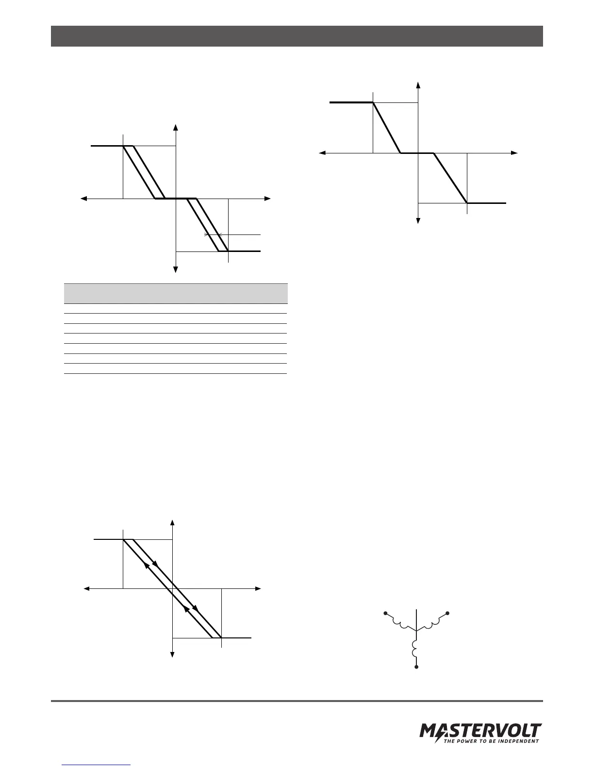
10.5.2 Voltage dependent Q control
This control law (Q – U control) produces an amount of
reactive power based on the actual grid voltage. Figure 10-9
shows an example demonstrating the available parameters.
Figure 10-9: Q – U control
Name Range Resolution Default
Value
Upper Limit 53%ind–53%cap 1% 44% cap
Lower Limit 53%ind–53%cap 1% 44% ind
VMIN 184 – 264 V 0,1 V 184 V
VMAX 184 – 264 V 0,1 V 253 V
V1 184 – 264 V 0,1 V 230 V
V2 184 – 264 V 0,1 V 230 V
Hysteresis 0 – 100 V 0,1 V 0 V
The reactive power values for the Upper and Lower Limits
are defines as a percentage of the nominal apparent inverter
power (Snominal). For example, a value of 20% cap
programmed in a CS20TL inverter, will correspond to
20.000VA * 20% = 4000var
Removing the hysteresis is possible by programming the
value to 0V. In case a hysteresis is provided, the V1 and V2
points will be centered inside width of the hysteresis. In
figures 10-10 and 10-11, two possible configurations are
shown with different parameters:
Figure 10-10: Example with V1 = V2 and Hysteresis > 0V
Figure 10-11: Example with Hysteresis = 0
Refer to www.mastervoltsolar.com for more information
about reactive power.
10.5.3 Constant Power Factor output
It is possible to fix the inverter phase angle regardless of the
output power by selecting the “Constant cos phi” control
law. Any value between 0,90 ind and 0,90 cap can be se-
lected.
10.5.4 Constant Reactive Power output
The “Constant Q” control law sets the inverter to generate
a fixed amount of reactive power regardless of the inverter
output power or the grid voltage. Like in the Q-U control law,
the reactive power setting is defined as a percentage of the
nominal apparent inverter power (Snominal).
10.5.5 Response Delay
The Response Delay determines how fast the inverter should
respond to changes in the output power or in the grid volt-
age, if the “cos phi – P control” or “Q – U control” laws are
used. Al larger Response Delay setting will make the inverter
respond slower.
10.6 USING AN ISOLATION TRANSFORMER
An isolation transformer may be necessary for several reasons:
1. To allow functional grounding of the PV array.
2. High Solar Array capacitance
3. Local regulations
10.6.1 Y-configuration
The secondary windings (on the inverter side) of the isolation
transformer must be in Y (wye, star) configuration with a
neutral connection available at the star point of the three
windings. Refer to figure 10-12 for a simplified installation
schematic.
Figure 10-12: 3-ph isolation transformer in Y-configuration
Lower
Limit
Q/S
nom
Upper
Limit
V
MIN
V
MAX
Inductive
Capacitive
Hysteresis
V1
V2
Lower
Limit
Q/S
nom
V
AC
Upper
Limit
V
MIN
V
MAX
Inductive
Capacitive
V1 = V2
Lower
Limit
Q/S
nom
V
AC
Upper
Limit
V
MIN
V
MAX
Inductive
Capacitive
V1
V 2
NL1 L2
L3