12
|
EN / SunMaster CS15TL RP / CS20TL RP / CS30TL RP
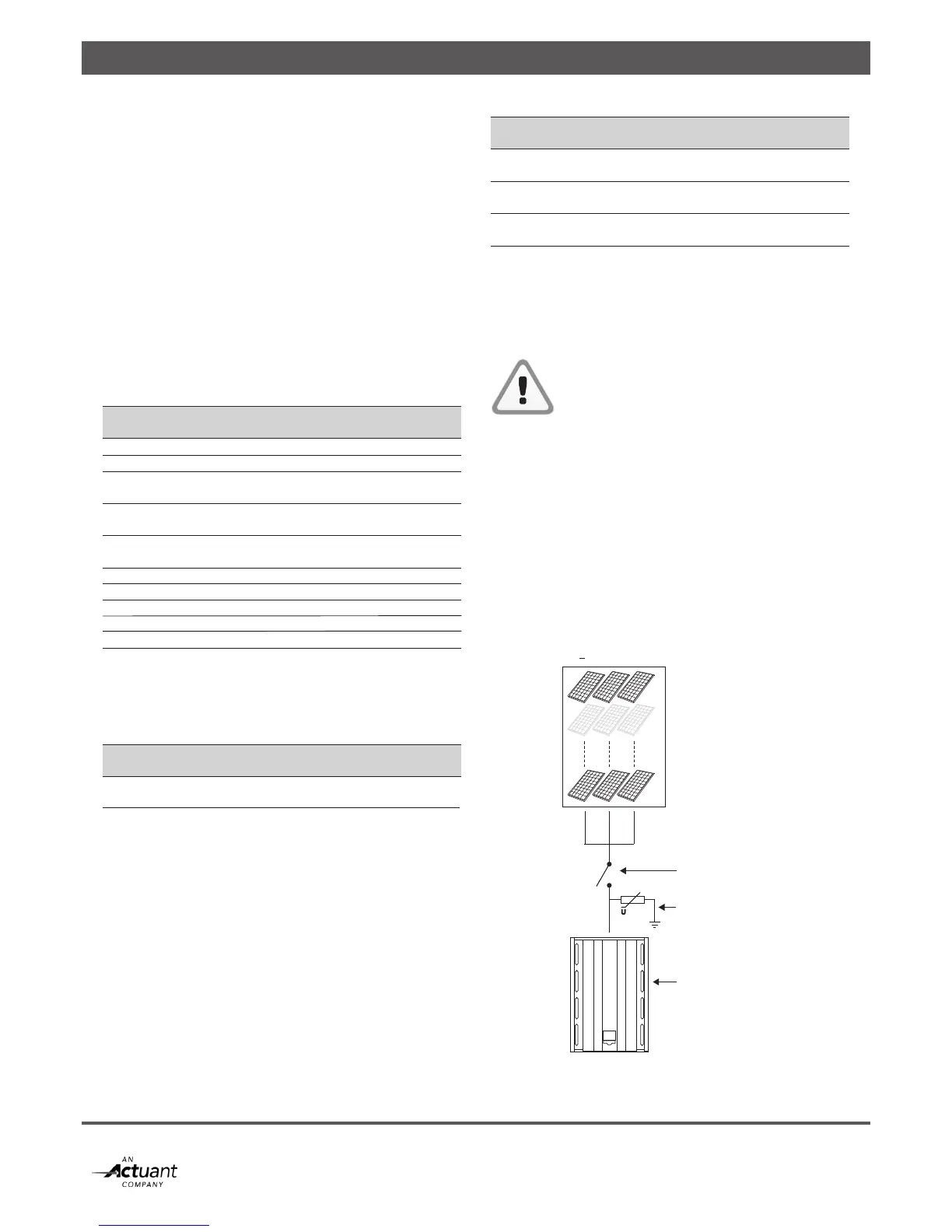
< 3 strings
U
Inverter
DC Switch
Surge protection
PV array
The SunMaster CS is designed to operate with a solar ar-
ray capacitance up to 6 µF. Larger array capacitances may
cause too large leakage currents, and can trip the internal
RCD protection.
If the RCD trips because of large PV array capacitance,
installing an isolation transformer may be necessary. Consult
your Mastervolt distributor for assistance.
4.5 AC OUTPUT SPECIFICATIONS
The SunMaster CS is intended for use in a permanent
installation, connected to a separately fused three-phase
AC branch to which no other equipment is connected. All
electrical connections must comply with locally applicable
installation codes and regulations.
The CS inverter is designed to operate in the following grid
conditions:
AC specifications
Model CS15TL RP CS20TL RP CS30TL RP
Nominal Power 15.000VA 20.000VA 30.000VA
Maximum Power 15.750VA 21.000VA 31.500VA
AC Voltage 3 Phase - 4 Wire Y
UGRID = 230VRMS +20%/–20%
Max. Phase
Current 3 x 24,2 ARMS 3 x 32,2 ARMS 3 x 46 ARMS
Max. Neutral
Current <1 ARMS
AC Frequency (50Hz) 45Hz – 55Hz
AC Frequency (60Hz) 55Hz – 65Hz
Max. Inrush Current 28.2A
Short circuit L-N 150A peak/12.9A RMS(3 cycl) during 8ms
Short circuit L-L 298A peak/21.8A RMS (3 cycl) during 4ms
4.5.1 Fusing
The SunMaster CS does not have internal fuses. External
fuses or circuit breakers are mandatory on every phase
according to the following ratings:
AC fuses
Model CS15TL RP CS20TL RP CS30TL RP
Fuse B
Characteristic 32A 40A 63A
Not installing a properly rated fuse (Icu > 2.1 kA) will pose a
safety hazard and will void the warranty of the inverter.
4.5.2 Wiring
The AC output is arranged in a 230/400V AC (3-Ph/N/PE)
Wye configuration. The neutral connection does not carry
any current, but must be connected to the inverter. The PE
connection must have a cross section as large as the largest
line conductor used, with a minimum of 4 mm2. For easy
installation, using a flexible cable type is recommended.
Refer to the locally applicable installation codes and
regulations for cable sizing.
AC wiring
Model CS15TL RP CS20TL RP CS30TL RP
Minimum cable
cross section 4 mm
2
6 mm
2
10 mm
2
Maximum AC
connector capacity 10 mm
2
16 mm
2
Flexible cable
outer diameter 20 mm 25 mm
4.5.3 RCD
The SunMaster CS is equipped with an internal RCD, refer to
specifications for tripping values. If an external RCD is used,
Mastervolt advises to use A, B, or AC sensitive devices with
a trip current of at least 300 mA.
CAUTION!
If you use RCD’s in your installation, connect
maximum one CS inverter to an RCD
4.6 LIGHTNING PROTECTION
In a solar installation, precautions must be taken to avoid
damage from surges induced by lightning. The CS inverter
is equipped with class III (micro) protection devices against
over voltages on all DC, AC and communication
connections. Additional external surge protection and use of
flexible cable is strongly recommended. StringMaster string
boxes feature class II surge protectors and are available from
Mastervolt. When used, surge protectors must be installed
less than 10m away from the inverter.
Figure 4-4: Surge protection in a PV installation