14
|
EN / SunMaster CS15TL RP / CS20TL RP / CS30TL RP
5.3 MOUNTING THE INVERTER
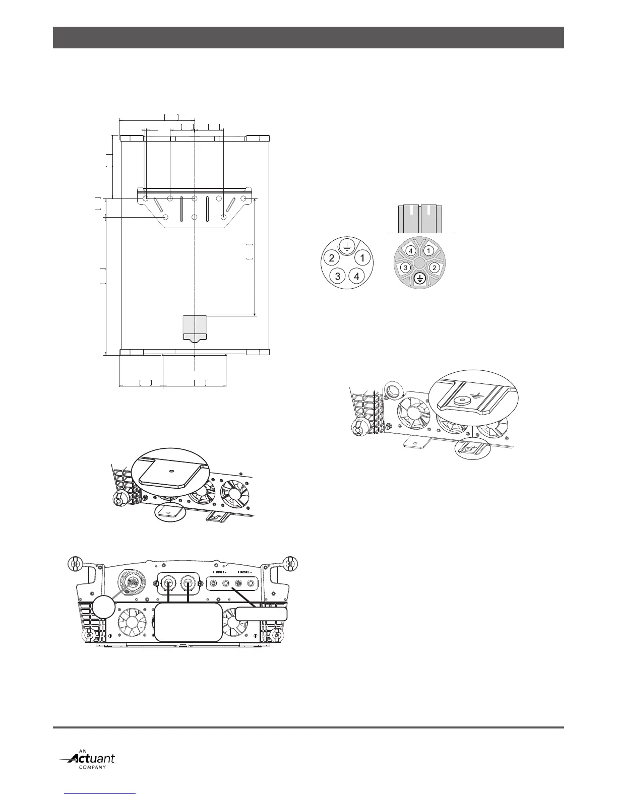
Fix the CS inverter to the wall, starting with the mounting
bracket. See gure 5-3. Use suitable screws and plugs.
Figure 5-3: Drilling dimensions of bracket and display
After hanging the SunMaster CS to the bracket, secure the
enclosure to the wall using the fixing plate. See figure 5-4.
Figure 5-4: Fixing plate
Figure 5-5: Bottom view of the SunMaster CS connections
See figure 5-5.
AC connector: refer to section 5.4,
Communication module: refer to chapter 7,
PV input: refer to section 4.3.
5.4 AC 3-PHASE CONNECTOR
The AC connector has five wire terminals, figure 5-6 shows
the connector. Connect PE first (yellow-green). On the
CS30TL connector, the PE terminal is located at the bottom
when the two white markings at the other side of the
connector are facing upwards.
Protective Earth
1. Line 1 (L1)
2. Line 2 (L2)
3. Line 3 (L3)
4. Neutral (N)
Figure 5-6:
AC 3-phase connector for CS15TL RP and CS20TL RP (left) and for
CS30TL RP (right)
A ground stud has been provided, see figure 5-7.
Figure 5-7: Ground stud
5.5 DC CONNECTORS
The DC connectors on the SunMaster CS are compatible
with connectors of the MC 4 type.
105M6 4,13
188 7,41 270 10,6
323 12,73
272 10,7
80 3,15
592,49 23,33
488 19,21
125 4,92
AC
Communication
module
PV input