30
|
EN / SunMaster CS15TL RP / CS20TL RP / CS30TL RP
Figure 10-1
Figure 10-2
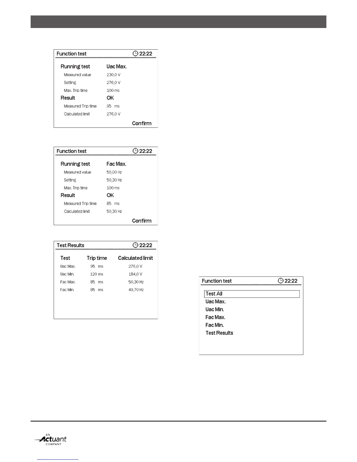
Figure 10-3: Function test summary
Uo Max-TEST (Uac Min-TEST)
Figure 10-1 shows:
Measured value: = the actual grid voltage;
Setting: = the set maximum / minimum inverter
voltage limit
Max. Trip time = Maximum time for inverter to shut
down after tripping
During this test the high (low) voltage limit is changed with
Rate -11.5V/sec (+11.5V/sec) until it trips: it reaches the
actual grid voltage. The time to trip is called Test duration.
The time the inverter needs to shut down after tripping is
called the Trip Time.
Result OK if the calculated limit is within range.
Trip Time Measured time between tripping and inverter shut
down Calculated limit Calculated Uac Max (Uac Min), equals
Measured value plus (minus) Rate x Test duration
Fac Max-TEST (Fac Min-TEST)
Figure 10-2 shows:
Measured value: = the actual grid frequency;
Setting: = the set maximum / minimum inverter
frequency limit
Max. Trip time = Maximum time for inverter to shut
down after tripping
During this test the high (low) frequency limit is changed with
Rate -0.05Hz/sec (+0.05Hz/sec) until it trips: it reaches the
actual grid frequency. The time to trip is called Test duration.
The time the inverter needs to shut down after tripping is
called the Measured Trip Time.
Result OK if the calculated limit is within range.
Measured Trip Time Time between tripping and inverter shut
downCalculated limit Calculated Fac Max (Fac Min), equals
Measured value plus (minus) Rate x Test duration
Figure 10-4: Function test selection