Comet Executive Gas Repair
7-15
Required Tools
Bar stock:
1/4”
3/8”
•
Perform only when the unit is OFF
with power disconnected and COOL.
1. Turn power OFF at the main disconnect
switch.
2. Open both endframe doors.
3. Locate the feed ribbons drive roll tension
adjustment bolts (Figure 7-2, A). There is
one on each side of the machine.
4. While holding each adjustment bolt in
place, loosen its locknut (Figure 7-2, B).
5. Turn each bolt the same number of turns
counterclockwise until the ribbons are
easily moved by hand.
6. Pull the feed ribbons around their tracks
until all the lacing clips are accessible and
aligned at the front of the unit.
7. Remove all the connecting pins from the
feed ribbons. Position the feed ribbons
away from the drive roll.
8. Use a small piece of 1/4” bar stock to
check the spacing between the feed table
and ironing cylinder at each end. There
should be a snug t. Use a small piece of
3/8” bar stock to check the spacing at the
center of the unit.
9. If the feed table is:
a) Not properly positioned, perform the
Adjusting Alignment and Position-
ing procedure next.
b) Properly positioned:
• Reconnect the feed ribbons. Make
sure the ribbons are below the ten-
sion adjustment rod, and also below
and between the feed ribbon guides.
• Stagger the positions of the lacing
clips to give atwork a smooth ow.
• Perform Feed Ribbon Tension
Adjustment on page 7-5.
Adjusting Alignment and Positioning
Required Tools
Bar stock:
1/4”
3/8”
Wrenches:
7/16” (2)
9/16” (2)
Perform only when the unit is OFF
with power disconnected and COOL.
1. Starting at either end of the unit, loosen the
bolts in the slotted holes on the underside
of the feed table (Figure 7-13, A).
2. Position the table 1/4” (6 mm) from the
ironing cylinder. Tighten the bolts to se-
cure the table in that position.
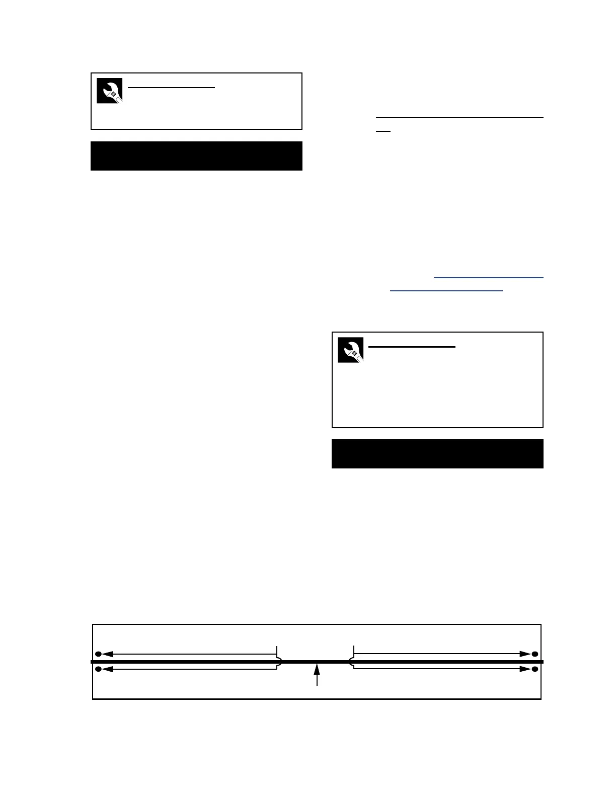
Figure 7-13: The slotted holes and threaded adjusting rod are used to properly align and position the feed table.
Position Adjustment Bolts (A)
Tension Adjustment Rod (B)