Setup
Connections
maxon motor control
3-18 Document ID: rel4734 ESCON Servo Controller
Edition: November 2014 ESCON Module 50/5 Hardware Reference
© 2014 maxon motor. Subject to change without prior notice.
3.3.4 Digital I/Os
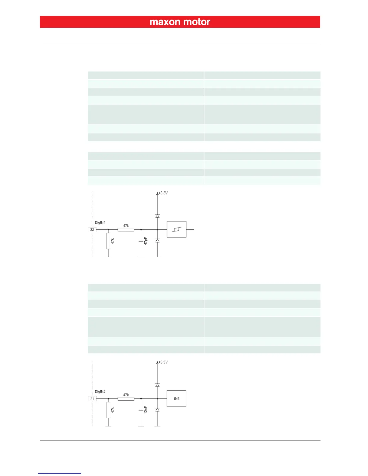
3.3.4.1 Digital Input 1
Figure 3-7 DigIN1 Circuit
3.3.4.2 Digital Input 2
Figure 3-8 DigIN2 Circuit
Input voltage 0…36 VDC
Max. input voltage +36 VDC/–36 VDC
Logic 0 typically <1.0 V
Logic 1 typically >2.4 V
Input resistance
typically 47 kΩ (<3.3 V)
typically 38.5 kΩ (@ 5 V)
typically 25.5 kΩ (@ 24 V)
Input current at logic 1 typically 130 µA @ +5 VDC
Switching delay <8 ms
PWM frequency range 10 Hz…5 kHz
PWM duty cycle range (resolution) 10...90% (0.1%)
RC Servo cycle duration 3…30 ms
RC Servo pulse length 1…2 ms
Input voltage 0…36 VDC
Max. input voltage +36 VDC/–36 VDC
Logic 0 typically <1.0 V
Logic 1 typically >2.4 V
Input resistance
typically 47 kΩ (<3.3 V)
typically 38.5 kΩ (@ 5 V)
typically 25.5 kΩ (@ 24 V)
Input current at logic 1 typically 130 µA @ +5 VDC
Switching delay <8 ms
 Loading...