Setup
Connections
maxon motor control
ESCON Servo Controller Document ID: rel4734
3-19
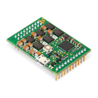
ESCON Module 50/5 Hardware Reference Edition: November 2014
© 2014 maxon motor. Subject to change without prior notice.
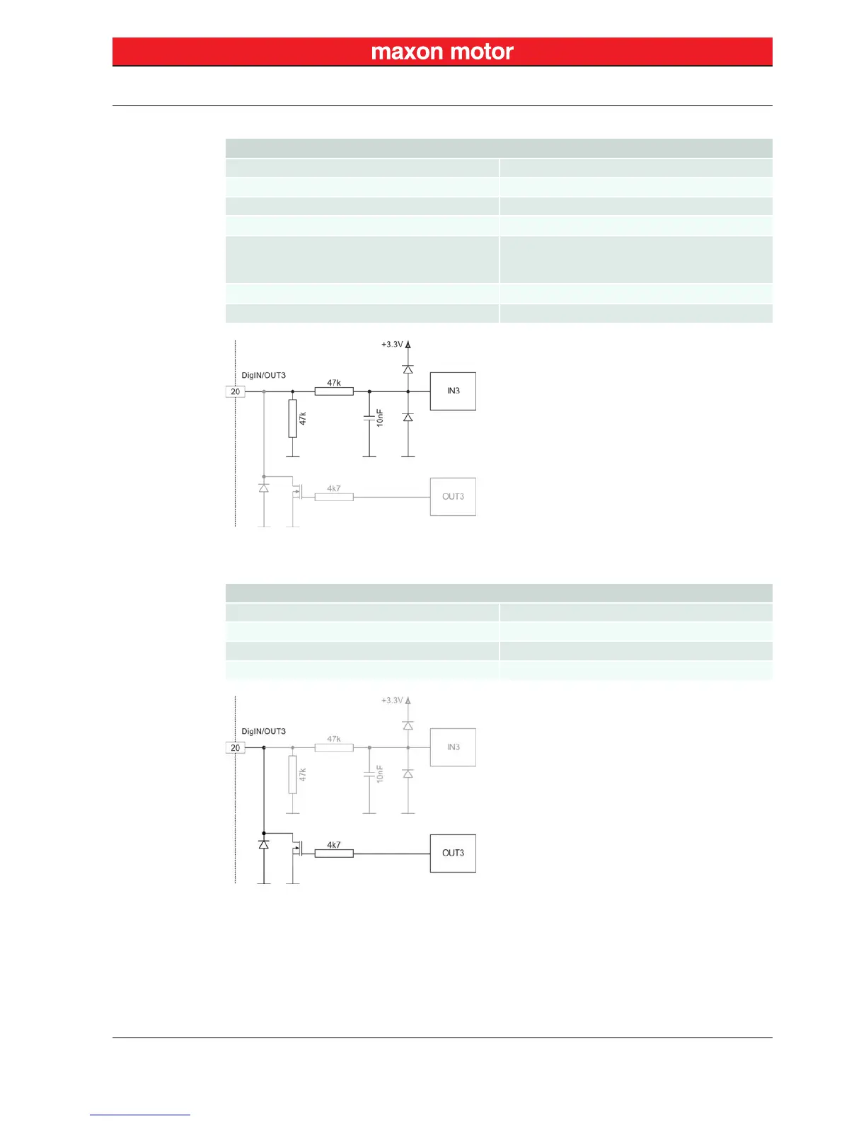
3.3.4.3 Digital Inputs/Outputs 3 and 4
Figure 3-9 DigIN3 Circuit (analogously valid also for DigIN4)
Figure 3-10 DigOUT3 Circuit (analogously valid also for DigOUT4)
DigIN
Input voltage 0…36 VDC
Max. input voltage +36 VDC
Logic 0 typically <1.0 V
Logic 1 typically >2.4 V
Input resistance
typically 47 kΩ (<3.3 V)
typically 38.5 kΩ (@ 5 V)
typically 25.5 kΩ (@ 24 V)
Input current at logic 1 typically 130 µA @ +5 VDC
Switching delay <8 ms
DigOUT
Max. input voltage +36 VDC
Max. load current 500 mA
Max. voltage drop 0.5 V @ 500 mA
Max. load inductance 100 mH @ 24 VDC; 500 mA
 Loading...