Setup
Connections
maxon motor control
3-22 Document ID: rel4734 ESCON Servo Controller
Edition: November 2014 ESCON Module 50/5 Hardware Reference
© 2014 maxon motor. Subject to change without prior notice.
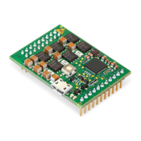
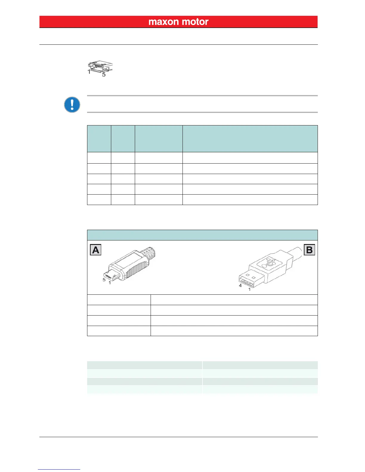
3.3.6 USB (J7)
Figure 3-14 USB Socket J7
Note
Column “Head B” (
Table 3-8) refers to USB terminals of your PC.
Table 3-8 USB Socket J7 – Pin Assignment & Cabling
Table 3-9 USB Type A - micro B Cable
J7 &
Head A
Head B
Signal Description
Pin Pin
11
V
BUS
USB BUS supply voltage input +5 VDC
2 2 D– USB Data– (twisted pair with Data+)
3 3 D+ USB Data+ (twisted pair with Data–)
4 – ID not connected
5 4 GND USB ground
USB Type A - micro B Cable (403968)
Cable cross-section According to USB 2.0 / USB 3.0 specification
Length 1.5 m
Head A USB type “micro B”, male
Head B USB type “A”, male
USB standard USB 2.0 / USB 3.0 (full speed)
Max. bus operating voltage +5.25 VDC
Typical input current 60 mA
Max. DC data input voltage –0.5…+3.8 VDC
 Loading...