October 2008 "2033ES / 2633ES" Service & Parts Manual - ANSI Specifications
Page 1-8
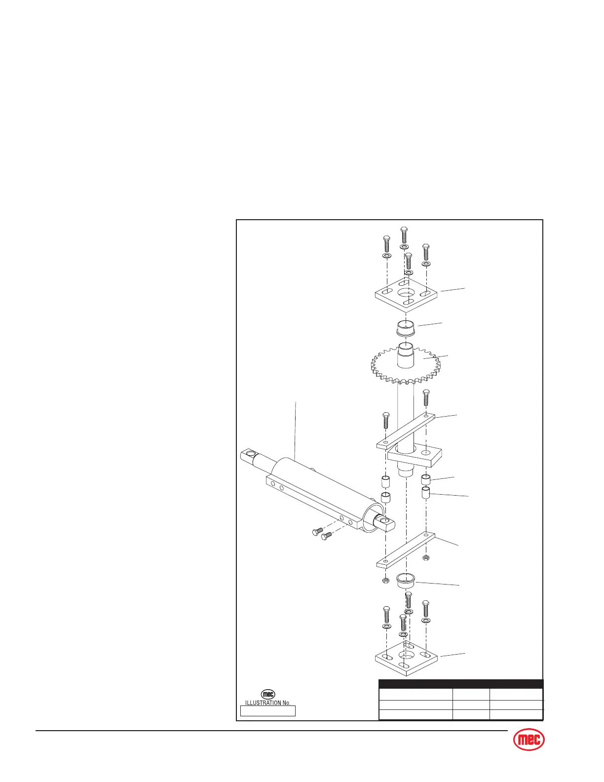
ART_2167 R1
Bearing
Shaft Plate
Shaft Plate
Bearing
Steering Shaft
Steering Link
Steering Cylinder
Steering Link
Bearing
Spacer
Cylinder Mount Bolts 102 - 112 138 - 152
Shaft Plate Bolts 86 - 96 113 - 130
Steering Link Bolts 26 - 28 35 - 38
TORQUE Ft. lbs. Nm
STEERING CIRCUIT
Note: Refer to
Hydraulic Manifold
and
Relief Pressure Adjustment Procedure
.
Refer to
Section 3
for Remove and Replace instructions.
Refer to
Parts Section E
for hose routing.
The steering system consists of the following components:
♦ Each wheel motor housings has a pivot and chain sprocket on the top.
♦ A hydraulic steering cylinder is mechanically linked via tie rods to two (2) chain-and-
sprocket assemblies (one
[1] for each motor housing).
♦ Steering is accomplished
hydraulically by using one
(1) double-acting cylinder,
and a 4-way 3-position
solenoid-operated, hydrau-
lic directional control car-
tridge valve.
Steer Cylinder
There is one (1) cylinder utilized in
the steering system. This cylinder is
a double acting type which requires
fluid flow to operate the cylinder rod
in both directions. Directing fluid
forces the piston to travel to one
side or the other, thereby extending
one rod end and retracting the
other.
Refer to the Mechanical Section of
this manual for cylinder disassem-
bly, or replacement.