October 2008 "2033ES / 2633ES" Service & Parts Manual - ANSI Specifications
Page 3-6
Front Drive Motors
There are two (2) hydraulic motors on the front axle. These can be damaged or leaks may occur;
repair or replace as necessary. Refer to
Section 1 - Hydraulics
for motor service and repair proce-
dure.
CAUTION: ♦ Clean all fittings before disconnecting hoses.
♦ Tag hoses for proper reassembly.
♦ Plug all openings to prevent contamination.
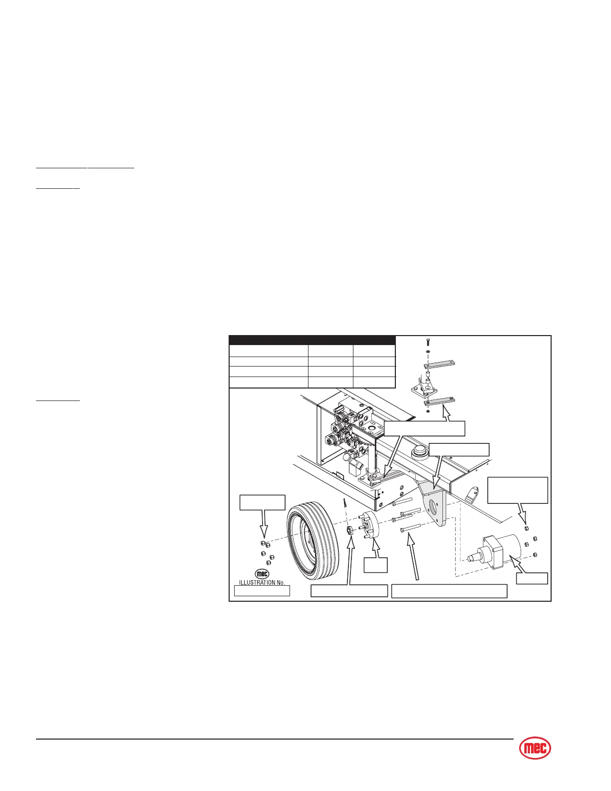
Front Drive Motors
Remove
1. Loosen the lug nuts.
2. Raise and support the front end of machine (see
Raising the Machine
).
3. Remove the wheel and tire assembly to access drive motor.
4. Disconnect the Steering Linkage (refer to illustration).
5. Remove the cotter key, motor shaft nut, and hub from the drive motor shaft.
6. Turn the motor housing to gain access to the motor and hose assemblies.
7. Disconnect hose assemblies
from drive motor.
8. Remove the cap screws and
remove the drive motor.
Replace
Installation is reverse of removal.
ART_2192
Steering Linkage
Motor Shaft Nut
Motor
Motor Mount Cap Screws
Motor Mount
Nuts
Motor Mount
Hub
Lug Nuts
TORQUE Ft. lbs. Nm
Lug Nuts 75 - 85 102 - 115
Motor Mount Bolts 65 - 72 88 - 97.5
Motor Shaft Nut 350 475
Steer Linkage Bolts 26 - 28 35 - 38