October 2008 "2033ES / 2633ES" Service & Parts Manual - ANSI Specifications
Page 5-14
ART_2791
1
2
6
8
4
3
7
5
1
2
6
8
4
3
7
5
RL-1
RL-1
RL-2
RL-2
17
2
17A
15
15
12
17
2
17A
15
Canadian Models
2033ES, S/N 8804100 - Current
2633ES, S/N 11100600 - Current
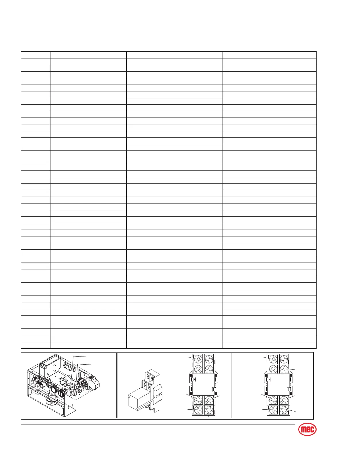
ITEM DESCRIPTION FUNCTION LOCATION
A1 Tilt Light, 28V Warn when Machine is Tilted Upper Control Box
A3 Level Sensor Activates Tilt Light Inside Lower Control Box
A5 Push-Button Switch Activates Horn Upper Control Box
A6 Horn, 12V - 48V (option) Activated by Operator Under Platform
A7 Overload/Motion Alarm (option) Warn of Movement Outside Lower Control Box
A8 Motion Light (option) Warn of Movement Front Left Corner of Machine
A9 Hour Meter Record Machine Usage Time Lower Control Panel
A11 Battery Indicator Show Battery Status Lower Control Panel
B1-4 6-V Deep Cycle Battery Power for Motor And Control Circuit Inside Battery Compartment
BD1 Battery Disconnect Switch Disconnect All Electrical Power Lower Control Box
CB1 Circuit Breaker, 15AMP Manual Control Circuit Protection Lower Control Panel
CH1 Battery Charger Recharges 24-VDC Battery Pack Inside Pump Compartment
CHRL1 Charger Relay Disconnect Electric when Charger ON Inside Charger
MC1 24-V Contactor Connects Battery (+) to Motor Inside Lower Control Box
D1 - D15 Circuit Board Diodes Directs Signal to Proper Location Inside Lower Control Box
R1 - R4 Circuit Board Resistors Inside Lower Control Box
D17 Diode w/Ring Terminals Suppression Diode Across Contactor Coil
ES1 Switch, Emergency Stop Shutdown All Moving Functions Lower Control Panel
ES2 Switch, Emergency Stop Shutdown All Platform Functions Upper Control Box
F1 Fuse, 200AMP Main Line Fuse Inside Lower Control Box
LS1 Limit Switch, Double Pole Enable Drive and High Speed Right Rear Corner of Machine
LS2 Limit Switch, Single Pole Drive Enable if Pothole Deployed On pothole Linkage
LS3 Limit Switch, Single Pole Drive Enable if Pothole Deployed On pothole Linkage
M1 Motor, 24V, 2HP Turn the Hydraulic Pump Pump Compartment
PWM Controller, DC 250AMP Changes the Motor Speed Inside Lower Control Box
POT1 Potentiometer, 20K Ohms Senses Operator Input Upper Control Box
RL-1 - RL-2 Relay, SPDT 2-Pole Cutout Function when Tilted Inside Lower Control Box
S1 Key Switch, N/O Contact Block Select Lower or Upper Controls Lower Control Panel
S2 Switch, Toggle Lift/Lower at Lower Controls Lower Control Panel
S3 Switch, Push Button Enable Other Functions at Platform Upper Control Box Handle
S4 Switch, Micro Right Turn Switch Upper Control Box Handle
S5 Switch, Micro Left Turn Switch Upper Control Box Handle
S6 Switch, Toggle Select LIFT or DRIVE Upper Control Box
S7 Switch, Micro Reverse or Lift Switch Upper Control Box
S8 Switch. Micro Forward or Down Switch Upper Control Box
S9 Switch, Toggle TORQUE Switch Upper Control Box
SOL1 Coil, Turn Right Solenoid Activate Turn Right Valve (SV1) Main Manifold
SOL2 Coil, Turn Left Solenoid Activate Turn Left Valve (SV1) Main Manifold
SOL3 Coil, Decel/Brake Solenoid Activate Decel/Brake Valve (SV5) Main Manifold
SOL4 Coil, Lift Solenoid Activate Lift Valve (SV2) Main Manifold
SOL5-6 Coil, Torque Solenoid Activate Torque Valves (SV5)(SV6) Main Manifold
SOL7 Coil, Reverse Solenoid Activate Reverse Valve (SV3) Main Manifold
SOL8 Coil, Forward Solenoid Activate Forward Valve (SV3) Main Manifold
SOL11 Coil, Down Solenoid Activate Down Valve (SV9) Lift Cylinder