30 TORKEL 900-SERIES ZP-CS01E CS033663DE
6 EXTERNAL CURRENT MEASUREMENT
3] Set max current on TORKEL 2.
4] Set warning limits only on TORKEL 1.
5] Set the stop limits. The voltage and test
period (time) can be set on each individual
TORKEL. Stopping after a certain capac-
ity (Ah) is reached can only be activated on
TORKEL 1.
Note Only TORKEL No. 1 is to control the TXLs.
6] Set switch <F1> to the upper (ON) position
on the TXLs.
7] Then start the TORKEL that has the highest
number (when numbered as set forth above).
Now start the TORKEL with the second
highest number, then the third highest, etc.
Finally, start TORKEL 1.
Starting the TORKELs in this order prevents
the current from being higher than desired
at the beginning of the test.
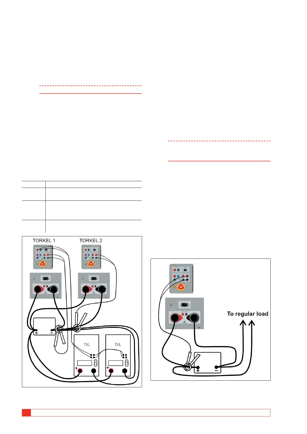
Two or more TORKEL and TXL units
TORKEL1 Measures the entire battery current.
TORKEL2 Measures all current except the current
through TORKEL1.
TORKEL3 Measures all current except the currents
through TORKEL2 and TORKEL1 (and so
forth).
The last
TORKEL
Measures only the current through itself
and the TXLs.
Example with two TORKELs. The first TORKEL regulate the TXLs
and the second TORKEL contributes in the total regulation.
1] Apply the clamp-on-probes as illustrated
above.
2] Set the desired total current (same value) on
both (all) TORKEL units
.
As a result, the maximum regulation capabil-
ity of all TORKEL units will be used. You do
not need to pay any attention to the mes-
sage reading “Cannot regulate” as long as it
does not appear on TORKEL No. 1.
3] Set warning limits only on TORKEL No. 1.
4] Set the stop limits. The voltage and test
period (time) can be set on each individual
TORKEL. Stopping after a certain capac-
ity (Ah) is reached can only be activated on
TORKEL No. 1.
Note Only TORKEL No. 1 is to control the TXLs.
Only TORKEL No. 1 is to be connected to the
PC.
5] Set switch <F1> to the upper (ON) position
on the TXLs.
6] Then start the TORKEL that has the highest
number (when numbered as set forth above).
Now start the TORKEL with the second
highest number, then the third highest, etc.
Finally, start TORKEL No. 1.
Starting the TORKELs in this order prevents
the current from being higher than desired
at the beginning of the test.
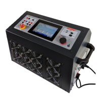
Constant current, regular load
connected
A current shunt can be used instead of the DC clamp-on
current probe but this requires opening the current path
and connecting the shunt in series.