38 TORKEL 900-SERIES ZP-CS01E CS033663DE
9 OPTIONAL EQUIPMENT
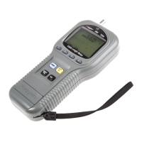
The other parts of the BVM system: AC Adapter, Power and
Signal Connector and cables.
Power & signal connector unit
The BVM units require external 24 DC power and RS-
485 data communications for operation. These func-
tions are provided by a combination of an external DC
power supply and a Power & signal connector unit”.
The Power & signal connector conversion is performed
within a single moulded plug that connects directly to
the laptop computer or other data acquisition device.
The Power & signal connector has an RJ-45 connector
that provides a connection to the first BVM unit in the
chain, and this connection provides RS-485 data and
power to all BVM units in the BVM string.
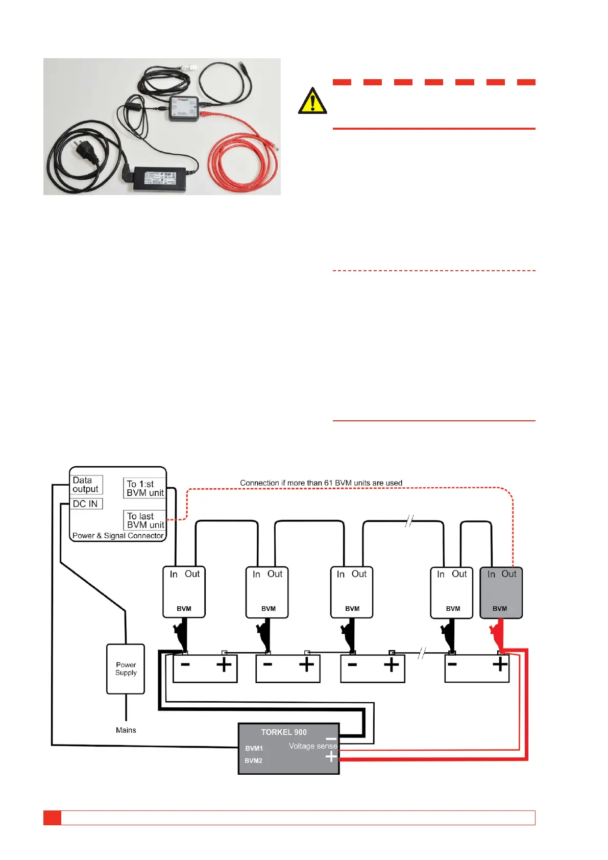
Test with BVM and TORKEL
WARNING
See the chapter "Safety" for safety pre-
cautions.
1] Connect the BVM units as shown in the con-
nection diagram, see below.
Each BVM is identical and can be connected
in any battery test position. Up to 120 BVMs
can be daisy-chained in a single battery bank
under test.
If you need more than 120 BVMs they must
be connected in two loops, see connection
diagram on next page.
Note The BVM units must be connected following
the battery cell sequence order. The BVM
connected to the “To 1:st BVM unit” port of
the Power and Signal connector must be con-
nected to the most Negative pole of the bat-
tery. The red dolphin clip shall be connected
to the most Positive pole of the battery. The
connection is the same regardless of the cell
numbering selected in TORKEL.
If more than 61 BVM units are connected
an extra cable is needed. See the connection
diagrams.
Fig.9.1 The BVM units must be connected following the battery cell sequence order. The red dolphin clip shall be connected
to the most Positive pole of the battery.