Hardware Installation
Memotec Inc. 3-23
3.9 E&M Wiring and Grounding
In a two-wire E&M application, connect wires 4 and 5 to the PBX R and T pair,
respectively. Refer to
Table 4-10.
• The R and T pair carry voice/fax analog signals between the SDM-9120/9220/
9230 and the PBX.
In a four-wire E&M application, connect wires 4 and 5 to the PBX R and T pair, and wires
3 and 6 to the PBX R1 and T1 pair, respectively.
• The R and T pair carry voice/fax analog signals from the SDM-9120/9220/9230
to the PBX.
• The R1 and T1 pair carry voice/fax analog signals from the PBX E&M tie trunk
to the SDM-9120/9220/9230.
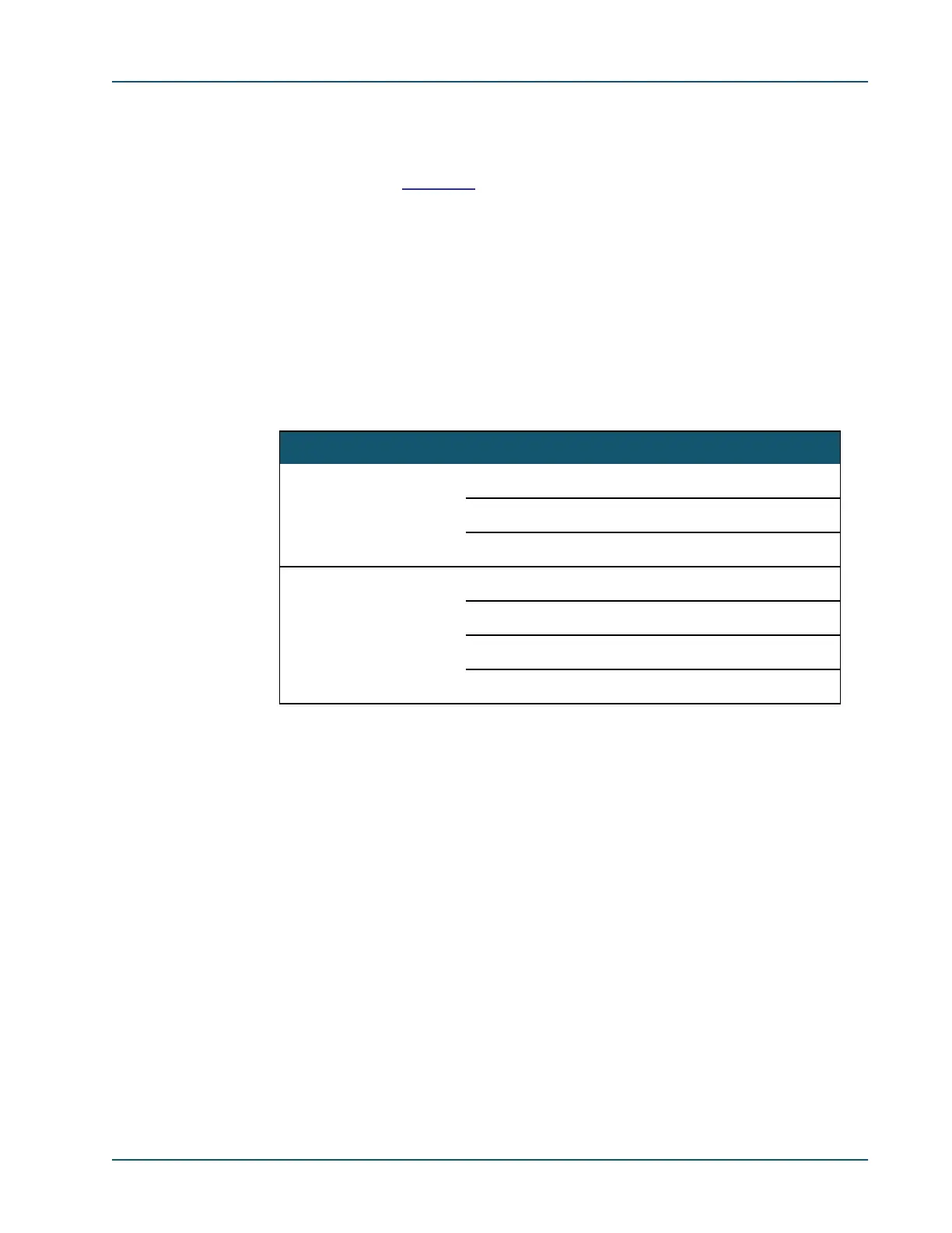
Connect the signaling wires as indicated in the following table:
When PBX-to-PBX E&M tie trunks are installed, the E lead of one PBX is normally
crossed over and connected to the M lead of the other PBX, and vice versa. See the first
connection scenario in “Four-wire E&M Connections” on page 3-24. In a multiplexing
application the crossover is accomplished digitally. Therefore, when connecting an analog
PBX to the E&M interface card, the E and M leads of the PBX connect to the E and M
E&M Signaling Type Pin No. Connect to PBX Lead
I, V 7 E
2M
8 SG (common ground)
II 7 E
8SG
2M
1SB
Table 3-2: E&M wiring
 Loading...