Description of device
PRM 10 E | Version 1.05 | EN 13
5 Description of device
5.1 Device view
Illustrations in this operating manual serve the general understanding
and may deviate from the actual design.
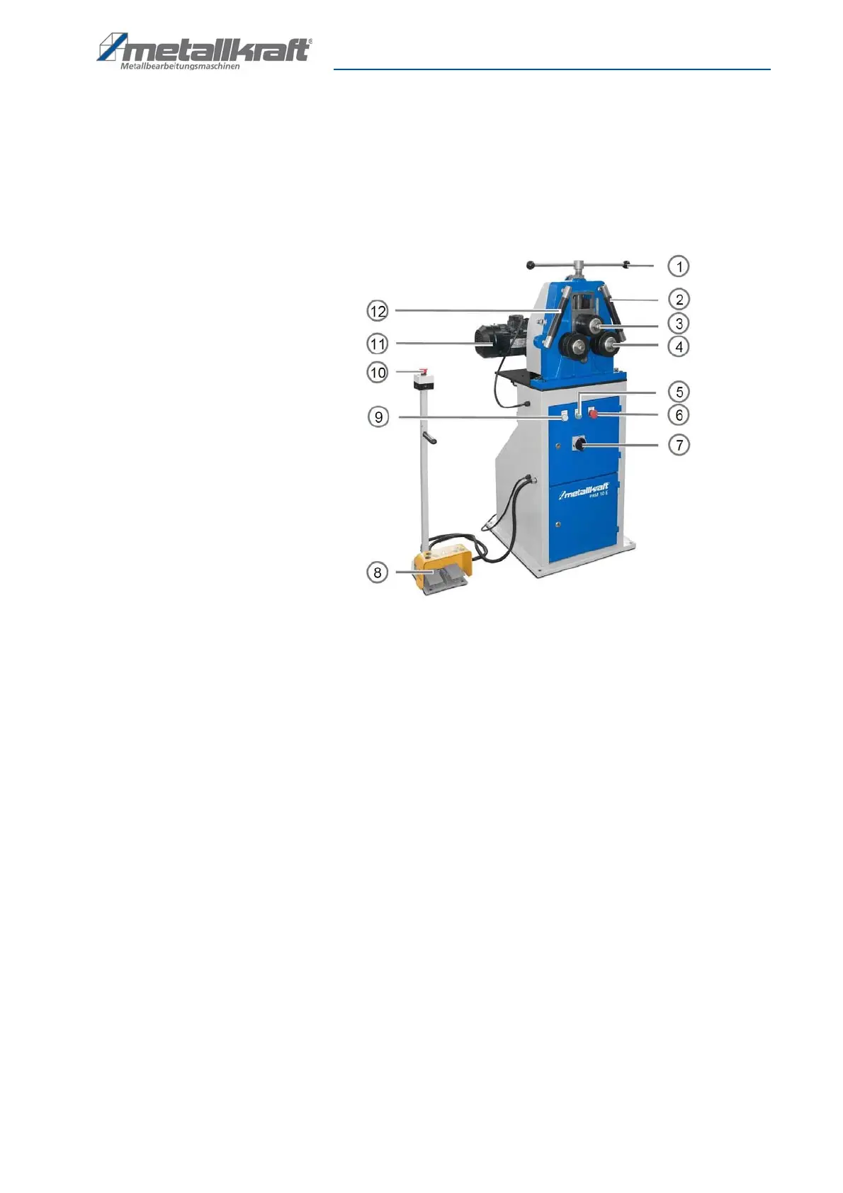
Fig. 5: Operating elements of the ring bending machine PRM 10 E
1 Spindle for height adjustment of upper
roll
2 Lateral guide roller on the right
3 Upper role
4 Lower roll right
5 START-Button
6 STOP-Button
7 Main switch
8 Control panel with pedals
9 Power indicator
10 Emergency stop button
11 Electric motor
12 Lateral guide roller on the left



 To Next Page