12 Technical Bulletin—TC-9100 Universal Controller
The parameters that are dynamically generated by the controller from the
analog inputs using the configuration parameters are listed below:
Table 5: Analog Input Dynamic Items
Item Tag Item Address
(Hex/Dec)
Description
AI1 01/01 Analog Input 1 Value
AI2 02/02 Analog Input 2 Value
AI3 03/03 Analog Input 3 Value
AI4 04/04 Analog Input 4 Value
AIH1 1E/30, Bit 1 1 = Analog Input 1 High Alarm
0 = No high alarm
AIL1 1E/30, Bit 2 1 = Analog Input 1 Low Alarm
0 = No low alarm
AIH2 1E/30, Bit 3 1 = Analog Input 2 High Alarm
0 = No high alarm
AIL2 1E/30, Bit 4 1 = Analog Input 2 Low Alarm
0 = No low alarm
AIH3 1E/30, Bit 5 1 = Analog Input 3 High Alarm
0 = No high alarm
AIL3 1E/30, Bit 6 1 = Analog Input 3 Low Alarm
0 = No low alarm
AIH4 1E/30, Bit 7 1 = Analog Input 4 High Alarm
0 = No high alarm
AIL4 1E/30, Bit 8 1 = Analog Input 4 Low Alarm
0 = No low alarm
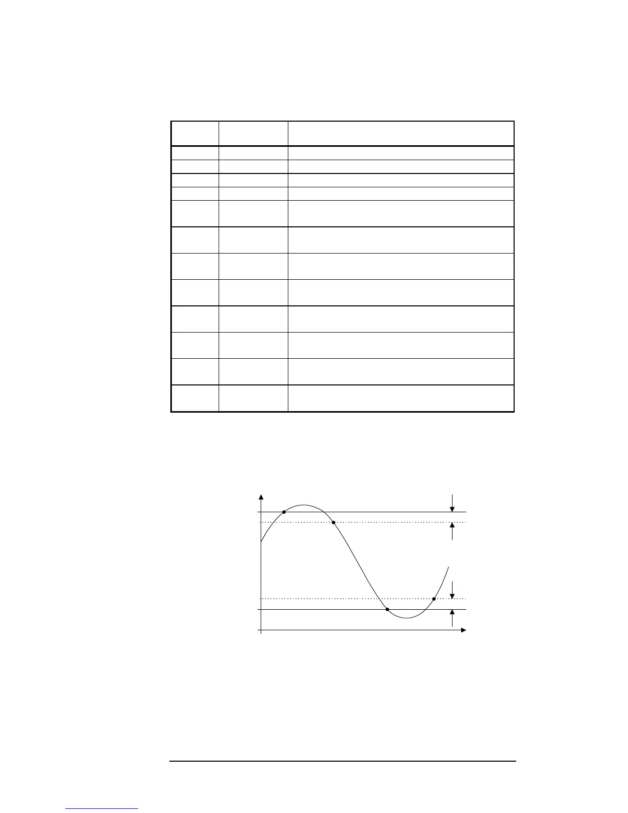
An alarm bit is set when the analog value is equal to the high or low
alarm value, and the alarm bit is cleared when the analog value comes
back into normal range by at least 2% of the range of the analog input,
defined by [HRI - LRI].
Low Alarm Value
2% of rangeNo alarm
Differential =
2% of range
No alarm
Low Alarm
High
Alarm
AI Value
High Alarm Value
Time
Figure 3: High and Low Alarms
When an analog input goes into high or low alarm, the DIAL Item bit is
set. For details, refer to the section titled Auto-dial Feature in this
document.
Dynamic
Parameters

 Loading...