36 Technical Bulletin—TC-9100 Universal Controller
The parameters to be defined for each programmable module using a
calculation algorithm are listed below. Refer to
Appendix 2 – Worksheet
2, or Appendix 1 – Table 1: Item List, for the Item addresses. In the table
below,
x in the PM Tag name is the programmable module number from
1 to 6.
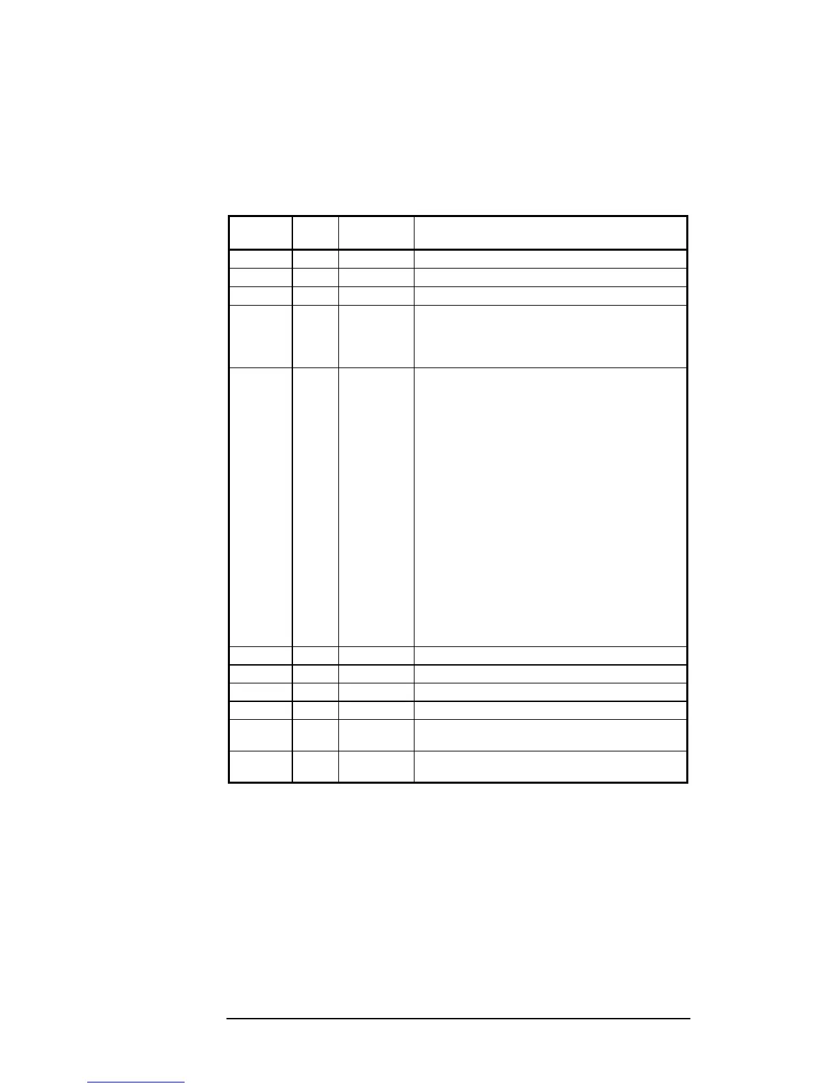
Table 13: Calculation Algorithms 7 to 12 Configuration Items
PM Tag Alg
Tag
Type Description
PMxK1 — Number Not used.
PMxI1@ I1@ connection
Input 1 (I1):
(optional)*
PMxI2@ I2@ connection
Input 2 (I2):
(optional)*
PMxI3@ I3@ connection
Input 3 (I3):
(optional)*
* When not connected, an input assumes a
default value of 1, or is excluded from a MIN or
MAX calculation.
PMxTYP TYP 2 Bytes
Algorithm Options
define the behaviour of the
programmable module.
Bits 5…1
Algorithm Number
in binary code:
00111 (07 hex) = Algorithm 7.
⇓
01100 (0C hex) = Algorithm 12.
Bits 8…6 Not used.
Bits 12…9
Define logic mode used by
Conditioning Logic
Variable 1
(values same as Variable 2 below)
Bits 16…13
Define logic mode used by
Conditioning Logic
Variable 2
:
0000 = none.
0001 = Window Open.
0010 = Occupancy Sensor.
0011 = Air Quality/Override.
0100 = Reverse Action.
0101 = General Alarm.
0110 = Low Limit (Anti-freeze).
PMxK2 K2 Number Constant used in the calculation.
PMxK3 K3 Number Constant used in the calculation.
PMxK4 K4 Number Constant used in the calculation.
PMxK5 K5 Number Constant used in the calculation.
PMxK6 K6 Number Constant used in the calculation if Conditioning
Logic Variable 1 is true.
PMxK7 K7 Number Constant used in the calculation if Conditioning
Logic Variable 2 is true.
Configuration
Parameters for
Calculation
Algorithms
7 to 12

 Loading...