Technical Bulletin—TC-9100 Universal Controller 9
Software Configuration
The software operating system of the TC-9100 Universal Controller
contains a number of modules which can be given operating and
configuration parameters and connected together to perform the desired
control function. Some of the modules condition physical inputs to
provide data to other controlling and calculation modules, and some
modules control the physical outputs, and the behaviour of all modules is
determined by the operating parameters. The modules are shown
graphically in Appendix 2 – Worksheet 1 – Connections, and the
configuration of each type of module is described in detail in the
following sections.
Parameter and connection data are stored in memory locations known as
“Items.” A complete list of all the Items is given in Appendix 1 – Table 1.
All Items have an address (given in hexadecimal and decimal notation)
and a tag for easy identification. Some Items contain analog information
in the form of numbers, some contain logical information in the form of
eight binary states (one byte) or 16 binary states (two bytes), and some
contain an integer number which is the address of another Item and
defines a “connection” between modules. The source of the connection is
the Item address of the analog output of a module and the destination of
the connection is the Item address of an analog input of a module. The
input (or destination) Items are identified by a tag with the “@” character.
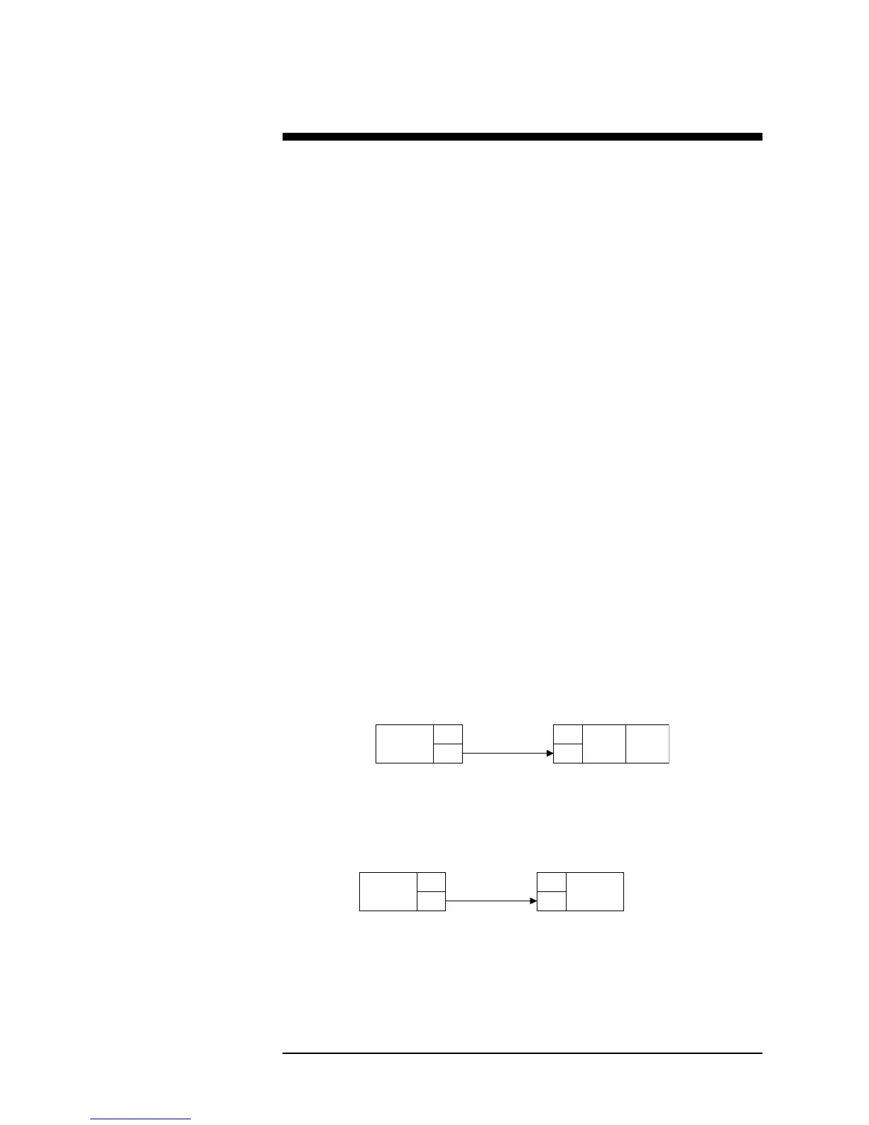
For example, the output of the module which measures Analog Input
Number 1 is found at Item Address 01, and has the tag name AI1. The
first input of Programmable Module Number 5 is found at Item Address
54 (hex) or 84 (decimal), and has the tag name PM5I1@. By entering the
value 01 in Item Address 54 (hex), a connection is made, whereby the
value of AI1 is transferred to the first input of Programmable Module
Number 5 as shown below:
01
PM5I1@AI1
01
54
Value
Connections to output modules are specified as part of the configuration
parameter item for each module. The first 5 bits contain the Item address
of the source of the connection. For example, when the Item Address 0A
(hex) is entered into the first 5 bits of Item Address 78 (hex) or 120 (dec),
the following connection is defined:
0A
OCN3OCM1
0A
78
Output 3Value
Worksheet 1 in Appendix 2 can be used to develop a control strategy by
making all the required connections graphically. The connection
information can then be entered into the Item address locations in
Worksheets 2 and 3. The parameters and data to define the operation of
the various software modules can also be entered into these worksheets.
Preparing a
Configuration

 Loading...