Technical Bulletin—TC-9100 Universal Controller 57
utc0swi
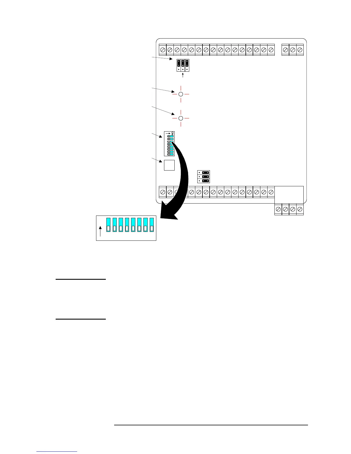
PWM
0-10 V
Address Switches
ON
23456781
JP4
JP3 (Factory Setting)
AO1a
AO1b
AO2
Jumpers for
Analog Output
Selection
Power LED
Receive/Transmit
LED
Address
Switches
Service Module
Socket
Figure 27: TC-9100 Controller Jumpers and Switches
When all jumpers and address switches have been set, and all connections
have been made and verified, 24 VAC power may be applied. The Power
LED should be lit. If the communications bus is active the R/T LED will
flash. If the Power LED is not lit, check the 24 V supply.
The operation of the TC-9100 Universal Controller can be verified using
the SM-9100 Service Module (or M9101 Software running on a PC). All
dynamic parameters may be viewed, and all supervisory system functions
can be executed using these configuration and commissioning tools.
For details of the SM-9100 operation, refer to the
SM-9100 User Guide
(MN-9100-6101).
Startup
Commissioning

 Loading...