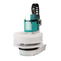
3.6 Mounting the drying flask
■■■■■■■■■■■■■■■■■■■■■■
18
■■■■■■■■
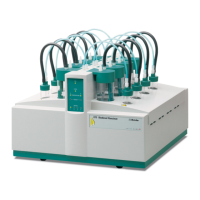
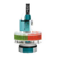
874 Oven Sample Processor
1
1
2
2
3
3
4
6.1805.0106.1805.010
6.1805.050
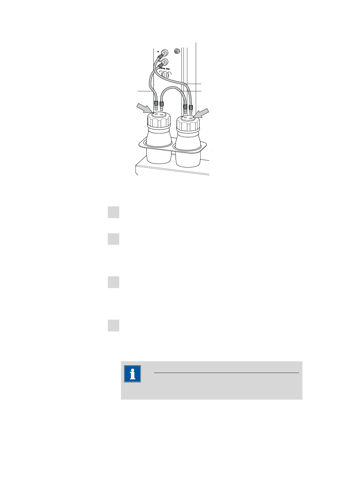
Figure 9 Mounting the tubings
Mount the FEP tubings as follows:
1
Insert the two drying flasks that have been prepared into the holders,
see previous illustration.
2
Screw one 6.1805.050 FEP tubing (18 cm length) to the gas out-
let (left-hand side of the tower, labeled to). Screw the other tubing
end on the front drying flask to the M6 connector without point
marking (see right-hand arrow).
3
Screw one 6.1805.010 FEP tubing (13 cm length) to the gas inlet
(left-hand side of the tower, labeled from). Screw the other tubing
end on the rear drying flask to the M6 connector with point marking
(see left-hand arrow).
4
Screw the second 6.1805.010 FEP tubing (13 cm length) tightly
onto the remaining M6 connectors of the drying flasks.
The marking Drying flask on the left-hand side of the tower dis-
plays the diagram for the tubing.
NOTICE
Tighten the screw connections well by hand.