■■■■■■■■■■■■■■■■■■■■■■
Table of figures
874 Oven Sample Processor
■■■■■■■■
V
Table of figures
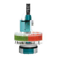
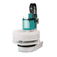
Figure 1 874 Oven Sample Processor front ...................................................... 8
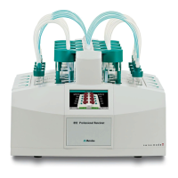
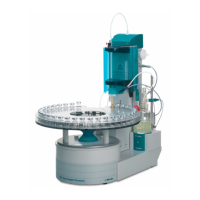
Figure 2 874 Oven Sample Processor rear ....................................................... 9
Figure 3 Sample rack 6.2041.720 ................................................................. 10
Figure 4 Mounting the sample holder ........................................................... 12
Figure 5 Mounting the needles ..................................................................... 14
Figure 6 Mounting the tubing ....................................................................... 15
Figure 7 Mounting the heating tubing .......................................................... 16
Figure 8 Preparing the drying flasks ............................................................... 17
Figure 9 Mounting the tubings ..................................................................... 18
Figure 10 Mounting the dust filter .................................................................. 19
Figure 11 External gas connector .................................................................... 20
Figure 12 Mounting the safety shield .............................................................. 21
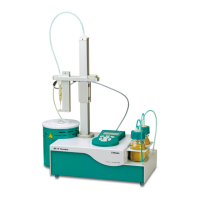
Figure 13 Coulometric KF titration cell ............................................................ 24
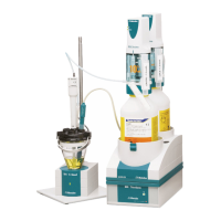
Figure 14 Volumetric KF titration cell ............................................................... 25
Figure 15 Attaching rack ................................................................................. 26
Figure 16 Adjusting the guide rod ................................................................... 27
Figure 17 Connecting the computer ................................................................ 28
Figure 18 MSB connections ............................................................................ 30
Figure 19 Connecting a dosing device ............................................................. 31
Figure 20 Connecting an MSB stirrer ............................................................... 32
Figure 21 Connecting the rod stirrer to the titration stand ............................... 32
Figure 22 Connecting the Remote Box ............................................................ 33
Figure 23 USB connectors ............................................................................... 34
Figure 24 Connectors of the Remote Box ........................................................ 39
Figure 25 Pin assignment of remote socket and remote plug ........................... 39
Figure 26 Rotational speed depending on the stirring rate ............................... 41