kajaaniMCA
i
– Installation, Operating & Service - 3.5 - W4610201 V2.5 EN
3.F.3. Alarm output
Connect the alarm output to the sensor’s Field Connec-
tion Board. The alarm output can be either normally-
closed or normally-open. A normally-closed relay out-
put is provided across terminals 17 & 19, a normally-
open output across terminals 18 & 19.
3.F.4. Grounding
Ground the shield of the connection cable between
Display Unit and MCAi sensor to the sensor electron-
ics’ ground bar, and to Display Unit terminal 16.
Ground the cables for current signals and alarm
output at one end only; for example, only ground them
at the automation system end.
3.F.5. Mains power
Connect the mains power, 90...260V, to the terminal
located on the left side of the Display Unit housing;
see Fig. 3.7.
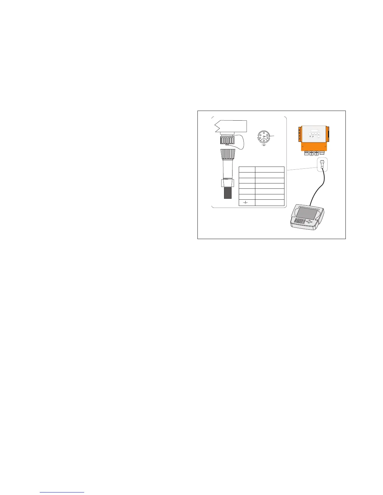
1
2
3
4
5
6
Display
Unit
Pin 1 +24 V
Pin 2 GND
Pin 3 R S -422
Pin 4 R S -422
Pin 5 R S -422
Pin 6 R S -422
cable shield
HART
RESULT
SAMPLE
IN FO DIAG MEAS
R
C S=3.08 %
Fig. 3.6. Connecting Communicator-i to the Display Unit.
3.F.6. Communicator-i
Connect the Communicator-i to the terminal located on
the lower edge of the MCAi Display Unit; Fig. 3.6.
3.F.7. HART® communicator
Using clip connectors, connect the HART® communi-
cator to the connecting pins on the keyboard card of the
MCAi Display Unit; see Fig. 5.5.
 Loading...