kajaaniMCA
i
– Installation, Operating & Service - A5.2 - W4610201 V2.5 EN
D
Min. 2 x D
(1 x D if Cs >8%)
Meas. line at a 90°
angle with regard to
pump axis
Min. 4 x D
(2 x D if Cs >8%)
Required straight
pipe section.
No valves or
other devices
protruding into
the pipeline.
FLOW
Installing an MCAi-F / MCAi-FS consistency sensor
NOTE: Before any installation work, make sure that the process pipeline is not pressurized
and that the installation will be safe!
1. Pay attention to the following requirements for the installation point:
- process temperature max. 100 °C (+212 °F)
- pH 2.5 – 11.5
- pressure 1.5–25 bar (22–363 psi)
- do not install the sensor to the suction side of a pump
- conductivity in accordance with the sensor specifications (see App. 1)
2. Make sure that the FLOW arrow on the sensor housing is aligned with the process
flow direction.
3. Make sure that the installation point and sensor position are in accordance with the
instructions.
4. Protect the sensor and Display Unit from direct heat radiation (sun).
5. Make sure that the clamping collar of the process coupling is properly tightened.
6. The sensors are ceramic – be careful not to damage them!
Installing (welding) the process coupling to a horizontal pipeline:
• Install to a horizontal pipe as shown below – the coupling must be within ±5º of the horizontal
plane.
• Notches on the coupling aligned with the pipeline, the smaller notch against the flow (label
on the coupling indicates the correct flow direction)!
Installing (welding) the process coupling to a vertical pipeline:
• Install to a vertical pipe as shown below – the coupling must be within ±5º of the horizontal
plane.
• Notches on the coupling aligned with the pipeline, the smaller notch against the flow (label
on the coupling indicates the correct flow direction)!
Installing to
horizontal pipeline
(view from the side)
VIRATUS
111 m m
(4 3/8")
a5
Installing to vertical pipeline
(view from the side)
Notches on coupling
aligned with pipeline
(view from
above)
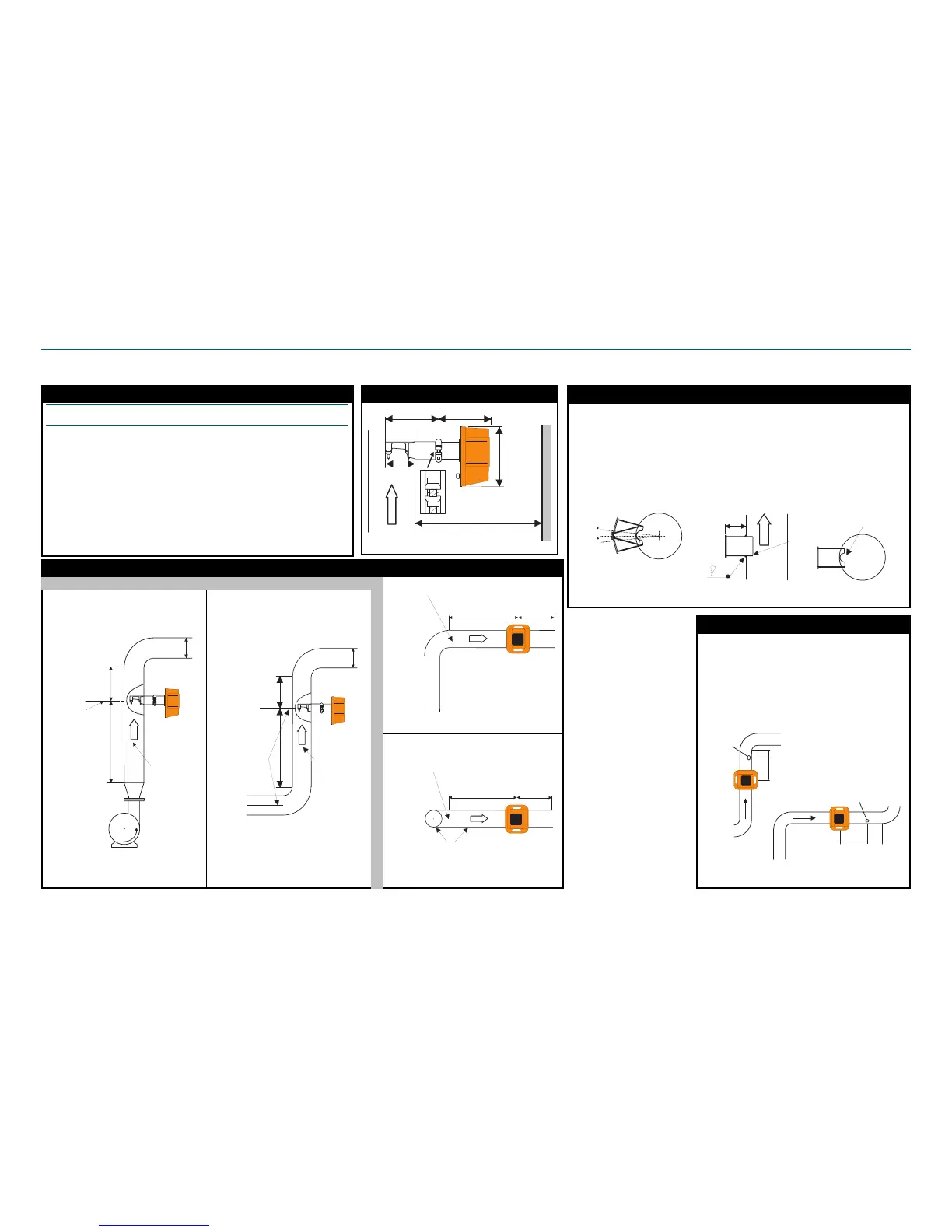
1. NOVE is usually installed after the MCA sensor. Make
sure that the distance between NOVE and MCA is ³ 2 x
D and ³1 x D of straight pipeline after the NOVE.
2. Install the NOVE at a 45° angle with respect to the MCA
measuring line.
3. If the NOVE cannot be installed after the MCA, install
it to the pipeline before MCA and make sure that there is
³4 x D of straight pipeline before the NOVE and ³1 x D
after it.
MCAi installation points
Check List for MCAi installation
MCAi-F &FS process coupling
D
FLOW
Meas. line
aligned with the
pipeline preceding
the bend.
Min. 4 x D
(2 x D if
Cs >8%)
Min. 2 x D
(1 x D if
Cs >8%)
Required straight
pipe section.
No valves or
other devices
protruding into
the pipeline.
Installation dimensions of the sensor
MCA
i
Required straight
pipe section.
No valves or
other devices
protruding into
the pipeline.
Min. 2xD
(1xD if
Cs>8%)
Min. 4xD
(1xD if Cs>8%)
FLOW
Vertical pipe
Horizontal pipe
MCA
i
Horizontal pipe
Required straight
pipe section.
No valves or
other devices
protruding into
the pipeline.
Min. 2xD
(1xD if
Cs>8%)
Min. 4xD
(1xD if Cs>8%)
FLOW
290 m m
(11 13/32")
272 m m
(10 23/32")
270 m m
(10 5/8")
m in. 600 m m (24")
161 m m
(6 11/32")
MCA
i
Nove
1xD
2xD
Vertical
pipeline
Installing a NOVE sampler
 Loading...