Connecons
User Guide
© 2023 Microchip Technology Inc. and its subsidiaries
DS-50003529B - 29
Figure 3-18. 6-Pin RJ11 to ICSP Adapter
Alternatively, the MPLAB ICD 5 using the adapter board provides an 8-pin 50-mil Microchip Universal
connection for the 6-pin and 8-pin ICSP interfaces.
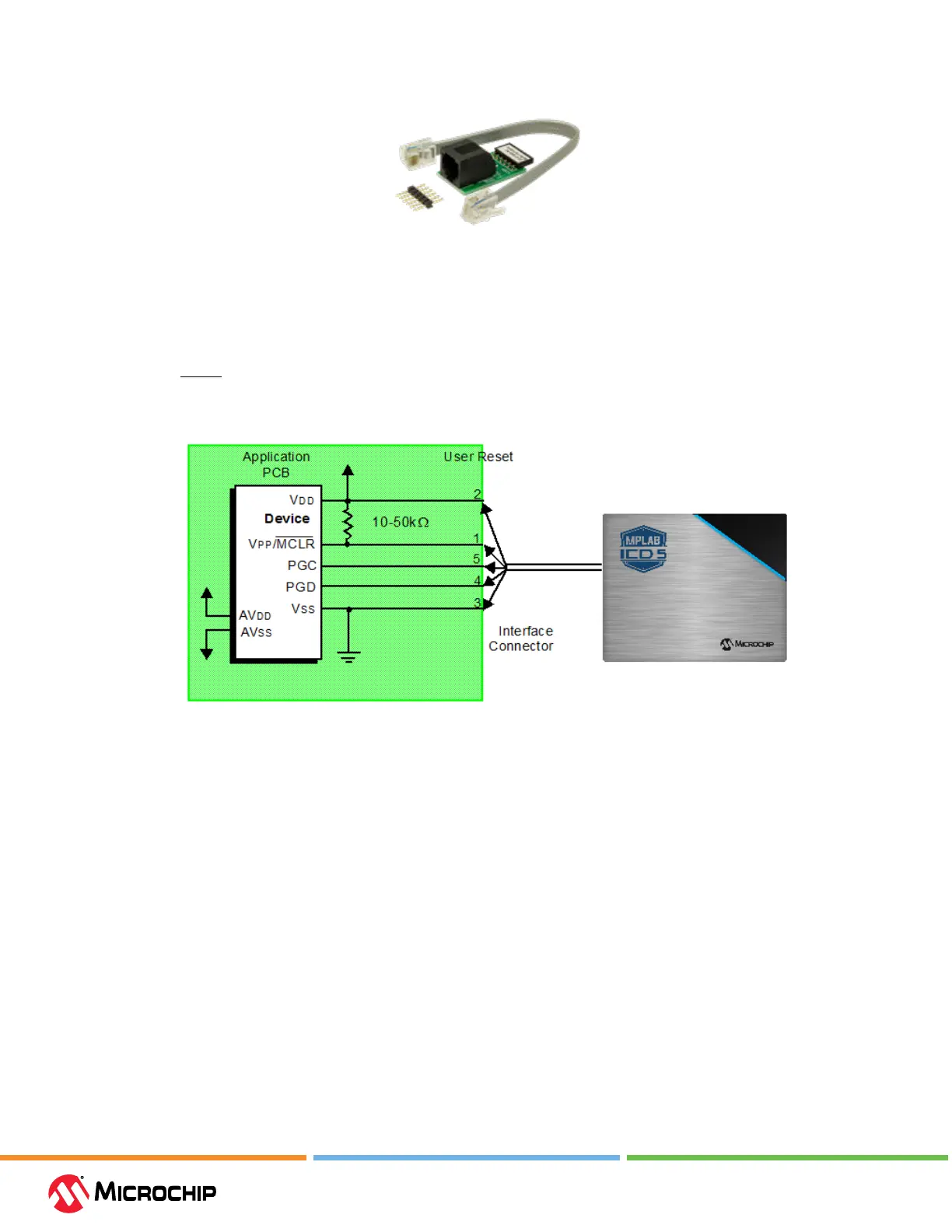
3.3.7.2 ICSP Target Connecon Circuitry
The gure below shows the interconnections of the MPLAB ICD 5 In-Circuit Debugger to the ICSP
connector on the target board. The diagram also shows the wiring from the connector to a device on
the target PCB. A pull-up resistor (usually around 10-50 kΩ) is recommended to be connected from
the V
PP
/MCLR line to V
DD
so that the line may be strobed low to reset the device.
Figure 3-19. Standard Connecon to Target Circuitry