About the Debugger
User Guide
© 2023 Microchip Technology Inc. and its subsidiaries
DS-50003529B - 7
Safety:
• Receive feedback from debugger when external power supply is needed for target.
• Supports target supply voltages from 1.2V to 5.5V.
• Safely power up to 1A with the PoE Power Supply or a PC capable of providing 3A on the USB
Type-C
®
connector.
• Protection circuits are added to the probe drivers to guard from power surges from the target.
• V
DD
and V
PP
voltage monitors protect against overvoltage conditions/all lines have over-current
protection.
• Power pins are physically isolated until voltage is determined to be safe for connection,
programmable resistor value, and direction (pull-up, pull-down, or nonexistent).
• Controlled programming speed provides exibility to overcome target board design issues.
• CE and RoHS compliant (conforms to industry standards).
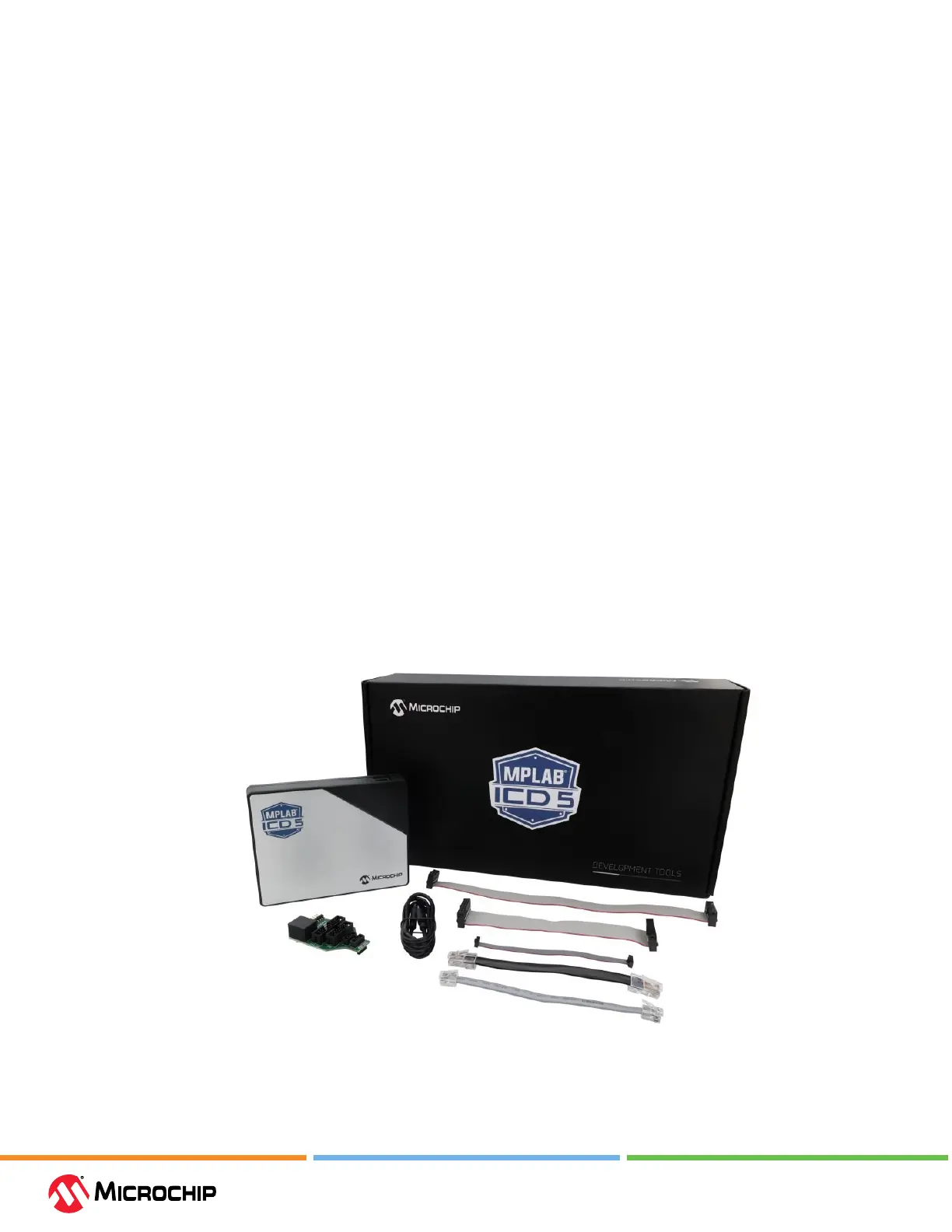
2.2 Components
The components of the MPLAB ICD 5 In-Circuit Debugger kit box are:
• The rectangular MPLAB ICD 5 unit housed in a durable black and metallic case, which is accented
with an LED indicator bar (see gure). On the sides of the unit are the USB connector, Ethernet
connector, power connector, as well as the communication and debug connectors
• A USB Type-C
®
to Type-C cable for default computer-to-debugger communication
• 14 pin cable: JTAG female at ribbon IDC connector, 15 cm
• 20 pin cable: JTAG female at ribbon IDC connector, 12 cm
• 8 conductor ICSP black modular cable, 6 inches
• 6 conductor ICSP gray modular cable, 6 inches
• 10 pin cable: cortex female at ribbon connector, 12 cm
• Figure 2-1. ICD 5 Box Contents