Hardware Specicaon
User Guide
© 2023 Microchip Technology Inc. and its subsidiaries
DS-50003529B - 86
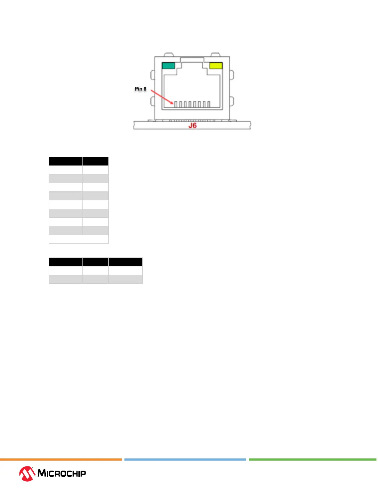
Figure 10-1. Ethernet Connector on MPLAB ICD 5
Table 10-2. Ethernet Connector Pinout
Pin Number Function
1 TX+
2 TX-
3 RX+
4 EGND
5 EGND
6 RX-
7 EGND
8 EGND
EGND: Enclosure ground
Table 10-3. Connector LEDs
LED Location LED Color LED Function
Top left Green LAN ACT
Top right Yellow LAN LINK
10.5 8-pin Communicaon Hardware
For full debugger communication with a target, connect the included RJ-45 cable into the debugger
modular RJ-45 jack at one end and an RJ-45 modular connector at the target end. Alternately plug
the cable into the Debugger Adapter Board to have access to many device legacy connections. For
details see 3.3 Target Connections.
For details on the 8-pin RJ-45 modular connector and modular cable, see the following sections.
10.5.1 Modular Connector - RJ-45
The ICD Tool uses an RJ-45 modular connector and cable to communicate with a target.
The modular connector pins are always numbered in the same order regardless of connector
orientation.