Connecons
User Guide
© 2023 Microchip Technology Inc. and its subsidiaries
DS-50003529B - 11
3. Connecons
The MPLAB
®
ICD 5 In-Circuit Debugger hardware setup begins by connecting power,
communications, and targets to the debugger. For legacy targets, an adapter board and cables are
provided. A Debugger Adapter Board is also provided to expand ICD5 connection capabilities to a
wide range of connector types.
3.1 Power and Self Test
MPLAB ICD 5 can be powered by USB-C power or Power over Ethernet (PoE). It does not use an
external power supply. The MPLAB ICD 5 can provide power to the target with PoE. PoE also powers
the tool if USB is unplugged. For customers who power their MPLAB ICD 5 directly from USB-C, it
will depend on the power capabilities of the host PC which MPLAB X IDE will detect once the USB is
connected. For details, see 10.2. Power Specications.
Power-up Self Test
The MPLAB ICD 5 unit performs a built-in self-test (or BIST) during power-up. Errors that occur
during this test are reported in the MPLAB X IDE or IPE Output window. Depending on the error, LED
colors may indicate the error as well.
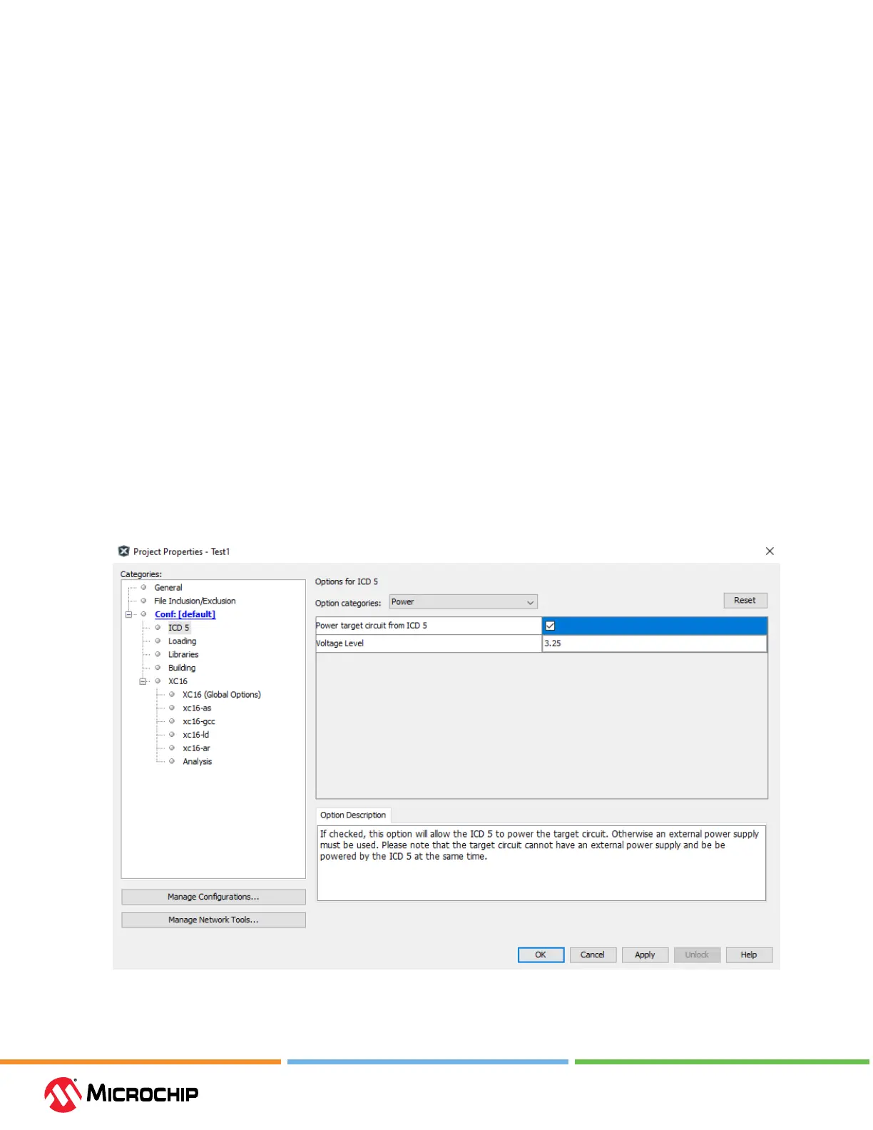
Power the Target
It is possible to power the target using the debugger. For details, see 10.2. Power Specications.
Select this option in the Project Properties window (see gure below). Also select the desired target
voltage.
Figure 3-1. Select Power to Target