Hardware Specicaon
User Guide
© 2023 Microchip Technology Inc. and its subsidiaries
DS-50003529B - 89
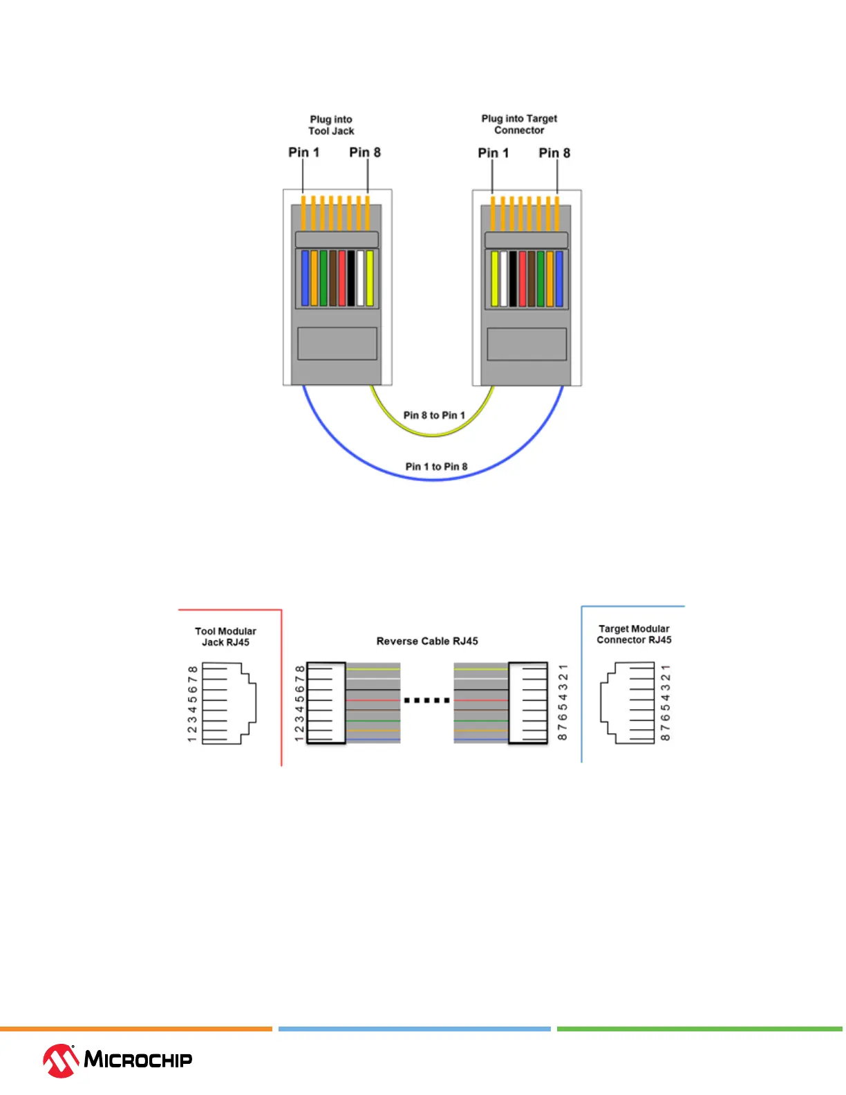
Figure 10-5. Reverse Wiring Cable
Pin numbering can be seen in the following diagram. Although the plugs are oriented dierently at
the tool and at the target, pin 1 is always pin 1 with relation to the plug.
Figure 10-6. Modular Connectors and Cable
10.6 Communicaon Hardware
For standard debugger communication with a target, use an adapter with the RJ-11 connector.
10.6.1 Connecng an RJ-11 Type Cable to an RJ-45 Jack on the Debugger
The MPLAB ICD 5 In-Circuit Debugger has an RJ-45 connector for communication to the target.
Connect the RJ-11 type cable into the RJ-45 connector by simply inserting it into the center of the
RJ-45 connector.
Refer to the gure below for the pinouts for this connection.