Operaon
User Guide
© 2023 Microchip Technology Inc. and its subsidiaries
DS-50003529B - 31
Hardware Breakpoints
The target OCD module contains several Program Counter comparators implemented in the
hardware. When the Program Counter matches the value stored in one of the comparator registers,
the OCD enters Stopped mode. Since hardware breakpoints require dedicated hardware on the
OCD module, the number of breakpoints available depends upon the size of the OCD module
implemented on the target. Usually, one such hardware comparator is ‘reserved’ by the debugger for
internal use.
Soware Breakpoints
A software breakpoint is a BREAK instruction placed in the program memory on the target device.
When this instruction is loaded, program execution will break, and the OCD enters Stopped mode.
To continue execution a “start” command has to be given from OCD. Not all Microchip devices have
OCD modules supporting the BREAK instruction.
4.3.1 AVR Device Interfaces
Note: If you are having problems with programming and debugging with AVR microcontroller
devices that use the UPDI/PDI/TPI interfaces, check Engineering Technical Notes (ETNs) for your
tool.
The AVR devices feature various programming and debugging interfaces. Check the device data
sheet for supported interfaces of that device.
• All AVR E/D devices and newer tinyAVR devices have a UPDI interface, which is used for
programming and debugging. AVR E/D devices also have the SPI interface for in-system
programming.
• Some tinyAVR
®
devices have a TPI interface. TPI can be used for programming the device only.
These devices do not have on-chip debug capability at all.
• Some tinyAVR devices and some megaAVR devices have the debugWIRE interface, which connects
to an on-chip debug system known as tinyOCD. All devices with debugWIRE also have the SPI
interface for in-system programming.
• Some megaAVR devices have a JTAG interface for programming and debugging, with an on-chip
debug system, also known as megaOCD. All devices with JTAG also feature the SPI interface as an
alternative interface for in-system programming.
• All AVR XMEGA devices have the PDI interface for programming and debugging. Some AVR
XMEGA devices also have a JTAG interface with identical functionality.
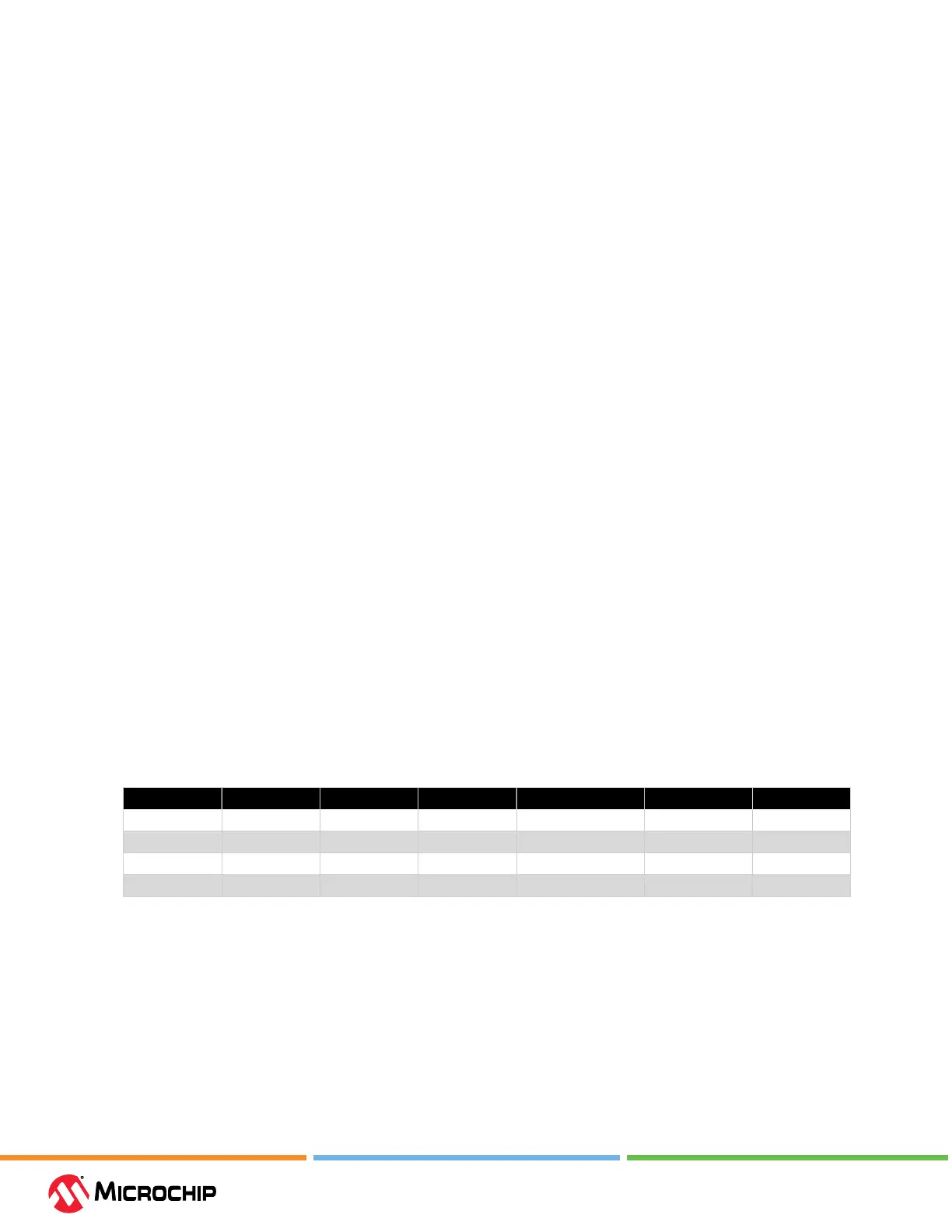
Table 4-2. Programming and Debugging Interfaces Summary
UPDI TPI SPI debugWIRE JTAG PDI
AVR E/D New devices New devices
tinyAVR New devices Some devices Some devices Some devices
megaAVR All devices Some devices Some devices
AVR XMEGA Some devices All devices
4.3.1.1 AVR E/D OCD - Features
The AVR E/D OCD is based on the UPDI physical interface, which is a single pin programming and
debugging interface. Other features include:
• Two hardware breakpoints
• Change of ow, interrupt, and software breakpoints
• Run-time read-out of Stack Pointer (SP) register, Program Counter (PC), and Status Register
(SREG)
• Register le read- and writable in Stopped mode