Operaon
User Guide
© 2023 Microchip Technology Inc. and its subsidiaries
DS-50003529B - 38
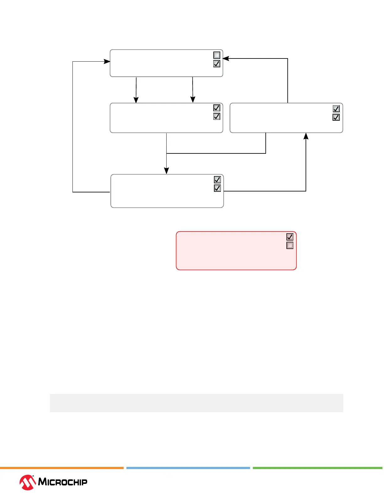
Figure 4-1. Understanding debugWIRE and the DWEN Fuse
Start debug session
Power toggle
(latches debugWIRE state)
Atmel Studio "Disable debugWIRE and close"
(disables debugWIRE module temporarily
and then clears DWEN fuse using SPI)
MPLAB® X IDE offers to do this automatically
if an attempt to connect using the SPI interface
fails due to debugWIRE being enabled
atprogram dwdisable
(atprogram disables
debugWIRE module temporarily)
Clear DWEN fuse
using SPI
Set DWEN fuse
using SPI
Intermediate state 1:
Fuse DWEN set
Fuse SPIEN set* (NB!)
Module debugWIRE disabled until power toggle
You can: Toggle power
DWEN
SPIEN
Default state:
Fuse DWEN cleared
Fuse SPIEN set
Module debugWIRE disabled
You can: Access flash and fuses using SPI
DWEN
SPIEN
Debug state:
Fuse DWEN set
Fuse SPIEN set
Module debugWIRE enabled
You can: Use debugWIRE
You cannot: Access fuses or flash using SPI
DWEN
SPIEN
Intermediate state 2:
Fuse DWEN set
Fuse SPIEN set
Module debugWIRE disabled
You can: Access fuses and flash using SPI
DWEN
SPIEN
Debug state (not recommended):
Fuse DWEN set
Fuse SPIEN cleared
Module debugWIRE enabled
You can: Use debugWIRE
To access flash and fuses, it is now necessary to
use the High-Voltage Programming interface
DWEN
SPIEN
4.3.1.6 Advanced Debugging (AVR
®
JTAG/debugWIRE devices)
I/O Peripherals
Most I/O peripherals will continue to run even though the program execution is stopped by a
breakpoint. Example: If a breakpoint is reached during a UART transmission, the transmission will be
completed and corresponding bits set. The TXC (transmit complete) ag will be set and be available
on the next single step of the code even though it normally would happen later in an actual device.
All I/O modules will continue to run in Stopped mode with the following two exceptions:
• Timer/Counters (congurable using the software front-end)
• Watchdog Timer (always stopped to prevent Resets during debugging)
Single Stepping I/O Access
Since the I/O continues to run in Stopped mode, care should be taken to avoid certain timing issues.
For example, the code:
OUT PORTB, 0xAA
IN TEMP, PINB
When running this code normally, the TEMP register would not read back 0xAA because the data
would not yet have been latched physically to the pin by the time it is sampled by the IN operation.
A NOP instruction must be placed between the OUT and the IN instruction to ensure that the correct
value is present in the PIN register.