Debugger Features
User Guide
© 2023 Microchip Technology Inc. and its subsidiaries
DS-50003529B - 48
available on all boards implementing the DGI device. The available interfaces can be read through
the USB protocol.
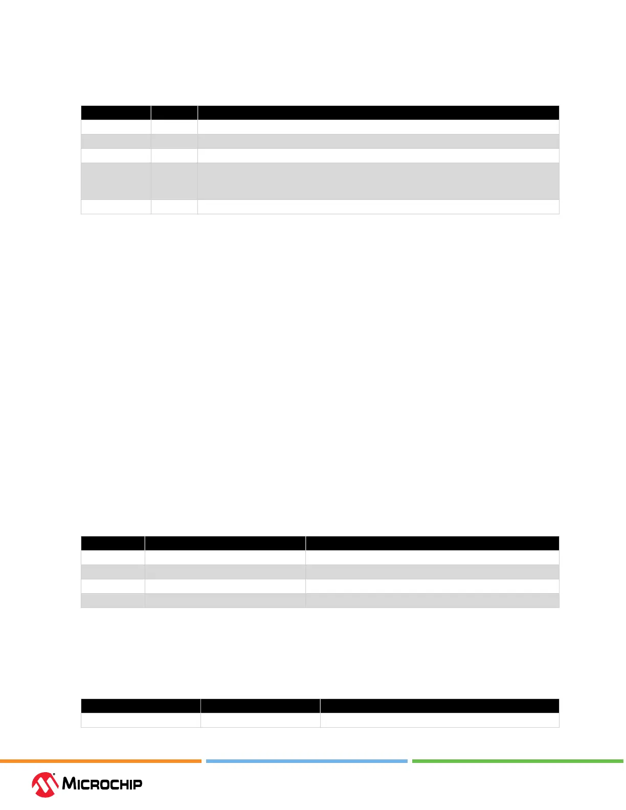
Table 5-2. List of Interfaces
Name Identier Description
Timestamp 0x00 Service interface which appends timestamps to all received events on associated interfaces.
UART 0x21 Communicates directly over UART in Client mode.
Power 0x40 (data) Receives data and sync events from the attached power measurement co-processors.
Debugger Polling 0x50 Polling of timestamped samples of the program counter,allowing an insight in the program
execution of the device.
For more information, see 5.6. Debugger Polling.
Reserved 0xFF Special identier used to indicate no interface.
5.2.1.1 Timestamp
The data returned over the timestamp interface is a sequential stream of timestamped packets of
data belonging to the interfaces that have timestamping enabled. The rst byte in each packet is the
interface identier and will decide how the rest of the packet must be parsed.
The timestamp is relying on a 16-bit timer, which is sampled and embedded into each packet. The
timer tick frequency can be read from the timestamp conguration. It is in the area of about half a
microsecond. When the timer overows, a packet will be embedded in the stream to indicate this
event. Note that if a data packet is being embedded as the timer overows, an overow packet will
not be embedded. Instead, it will be indicated in the header of the data packet.
All timestamped packets are generated from module interrupts within the DGI device, which can not
be interrupted by the timer overow interrupt. This means that there is a possibility that the timer
has overowed before the timer was sampled and embedded. To be able to keep the timestamp in
sync and accurate for such events the packets are also embedding the timer overow bit. This bit is
sampled after the timer itself, and can potentially be set even if the sampled timer value was in sync.
5.2.1.2 UART Interface
The UART source streams the raw values received on the UART interface.
On the Data Sources (left) pane, when the UART source is selected, the UART settings are displayed
on the lower section.
Note: Asynchronous serial protocols (e.g., UART protocols used by DGI UART and CDC Virtual COM
port interfaces) use the baud rates listed in 5.1. USB CDC Virtual COM Port.
Table 5-3. USART Sengs
Field Name Values Usage
Baud Rate 0-2000000 Baud rate for UART interface in Asynchronous mode
Char Length 5, 6, 7, or 8 bits Number of bits in each transfer
Parity None, Even, Odd, Mark, or Space Parity type used for communication
Stop bits 1, 1.5, or 2 bits Number of Stop bits
5.2.1.3 Power Interface
The Power interface measures the power consumption of the connected circuitry.
Select the Power interface beneath the debug tool DGI. Set up the interface using the controls under
“Power Settings.”
Table 5-4. Power Sengs Controls
Control Value Usage
Enabled Channels A Enable channel A only. Channel A is always enabled.