Chapter 2 System Components
2-28 HAWK MV-4000 Smart Camera Guide
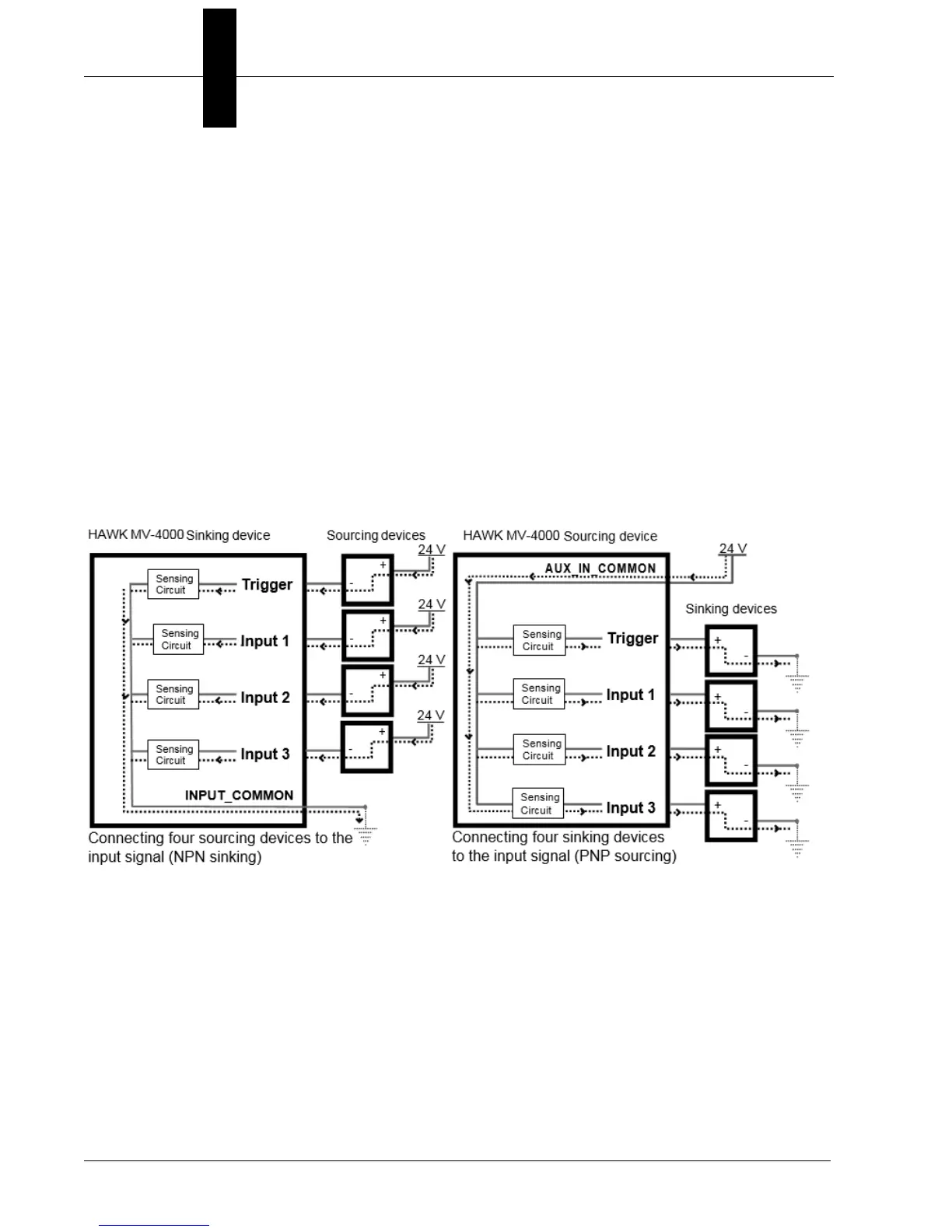
Connecting Devices to the Input Signals
HAWK MV-4000 input signals can be interfaced with a wide variety of devices (such as
proximity detectors). The HAWK MV-4000 input signals only detect when current flows
between their Input pin and Input Common pin. As such, an input signal must be
connected to a device that controls the flow of current. When current is detected, the
signal is reported as on; otherwise, it is reported as off. For information on the electrical
specifications of the on and off voltage levels, see the Electrical specifications section, in
Appendix C: General Specifications.
Each of the four available input signals has one dedicated pin (Trigger, Input 1, Input 2 and
Input 3) and shares its other pin (Input Common) with the other input signals.
You can connect the input signals in a sinking or sourcing configuration. Since the input
signals share a common pin, they must all be in a sinking configuration or all in a sourcing
configuration. The exact connection between the input signal, the connected device, and
the power source depends entirely on the type of device to which you connect. You should
essentially connect your device respecting the following:
(Equivalent circuit only.)
 Loading...