JTAG Programming
UG0451 User Guide Revision 7.0 17
tolerance ranges, see the SmartFusion2 SoC FPGA Datasheet. The board must supply JTAG voltage to
the VDDIOx pin of the device and the VJTAG pin of the programmer header.
In Libero SoC 11.8 SP3 and later versions, FlashPro will not detect VPP if the board contains only
RTG4/SmartFusion2/IGLOO2 devices. Leave VPUMP pin of the JTAG header floating if the board has
only RTG4/SmartFusion2/IGLOO2 devices.
If the board contains ProASIC3/IGLOO/Fusion/SmartFusion devices along with SmartFusion2/IGLOO2
devices in the JTAG chain, connect VPUMP of the ProASIC3/IGLOO/Fusion/SmartFusion device to the
JTAG header’s VPUMP pin.
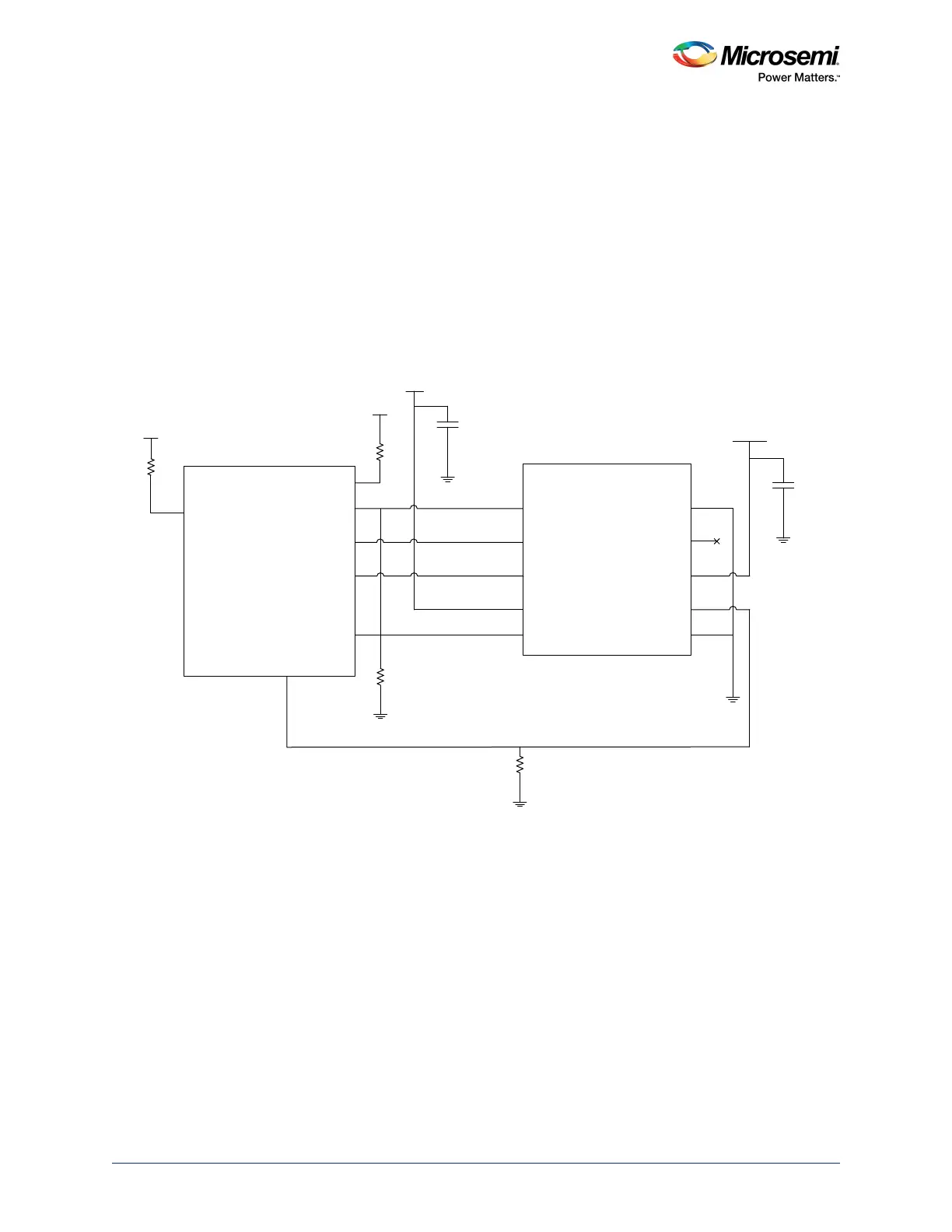
Microsemi recommends that VPP and JTAG power supply lines are kept separate with independent
filtering capacitors. For capacitor requirements, see the following figure. The bypass capacitor must be
placed within 2.5 cm of the device pins. For termination requirements of JTAG pins, see Tab le 6,
page 13.
Figure 6 •
JTAG Programming of a SmartFusion2 Device
JTAG_TCK
JTAG_TDO
JTAG_TMS
JTAG_TDI
JTAG_TRSTB
FlashPro4/
FlashPro5/
JTAG Header
TCK
TDO
TMS
*
VPUMP
TDI
GND
PROG_MODE
VJTAG
TRST
GND
1 KΩ
VPP
VDDJ
0.1
μF
Mfr. P/N: HTST-105-01-L-DV-A
Mfr.: Samtec Inc
0.1
μF
1
3
5
7
9
10
8
6
4
2
*
*When VPP = 2.5 V, do not connect this pin and leave it floating. Select Drive VPUMP option from FlashPro4 programmer settings.
1 KΩ
VDDJ
JTAGSEL
SmartFusion2/
IGLOO2
1 KΩ
VPP
10 K
DEVRST_N