Auto Update
UG0451 User Guide Revision 7.0 36
the device is not changed, therefore the device boot sequence continues, and the existing user design
powers up.
Four SPI slave select pins of the SPI_0 interface (SS4, SS5, SS6, and SS7) drive high during auto
programing (except 005, 010 devices). The remaining SPI_0 pins are tristated with weak pull up. These
four pins that drive high during auto update must not be used as control pins. The I/O level and drive
strength are based on the previous settings programmed into the device.
The target board must provide power to the VPP, VPPNVM, VDD, and VDDIOx (where x = SPI_0
interface bank number) pins.
For the recommended voltage ranges and pin locations, see the SmartFusion2 and IGLOO2 Datasheet
and the corresponding package pin assignment table.
For information about the I/O states during auto update, see State of SmartFusion2 and IGLOO2
Components During Programming, page 42.
8.1 Configuring the Device for Auto Update
There are two ways to configure the FPGA for auto update:
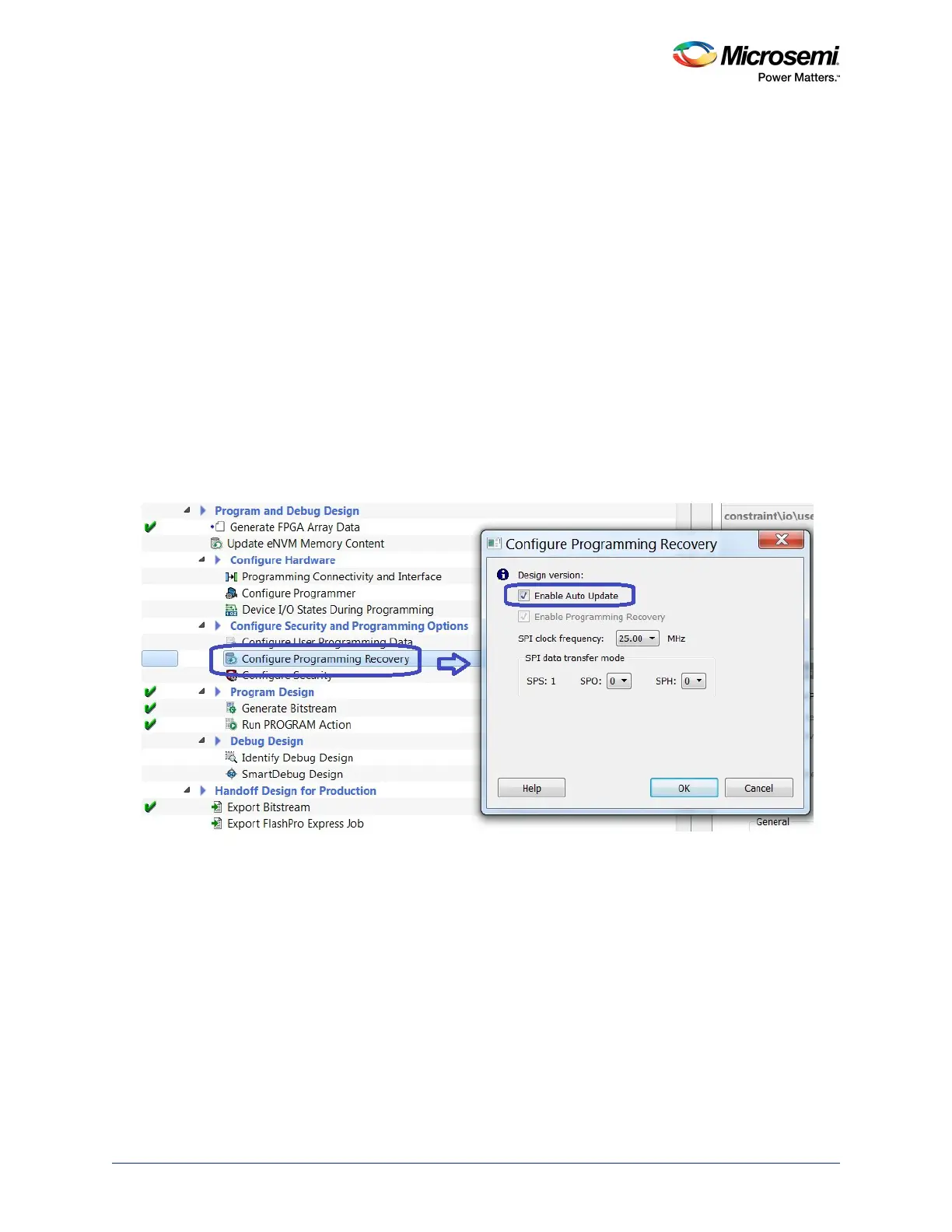
• Generate a bitstream with the auto update configuration in the Libero SoC software and program the
device to enable this programming mode, as shown in the following figure. For more information on
configuring the auto update, see the Libero SoC User Guide.
Figure 19 • Enabling Auto Update
• Factory preconfigures the device before shipping. It can be either of the following:
• In house programming (IHP) at the factory.
• Programmed with a preconfigured image using a standalone Silicon Sculptor 3 programmer.