In-Application Programming
UG0451 User Guide Revision 7.0 31
7.1.3 Program
The device is automatically placed in the F*F state before programming commences and the F*F entry
message is transmitted. If the programming operation is successful, the device goes through a power-
on-reset sequence generated by the system controller.
However, the user application must execute another system reset in addition to system controller reset
as soon as the IAP system service is completed, otherwise the LSRAM block might be inaccessible.
System reset can be generated using the tamper macro, which can be instantiated from the Libero SoC
Catalog. Immediately after IAP, user logic (that is, an FSM module) can check LSRAM access. If the
access is denied, then user logic generates a reset signal that can trigger the tamper macro to execute
the system-level reset. The RESET function in the tamper macro configuration window must be enabled.
For detailed implementation along with reference design, see the SmartFusion2 SoC FPGA In-
Application Programming Using PCIe Interface Demo Guide or Implementing Programming Recovery
and In-Application Programming Features Using Ethernet Interface for SmartFusion2 Devices Demo
Guide.
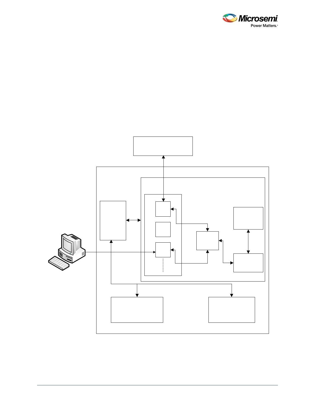
Figure 16 • SmartFusion2 In-Application Programming
External SPI Flash
(New bitstream)
System
Controller
SPI_0
UART
USB
Cortex-M3
Processor
AHB Switch
APB Bus
Fabric eNVM
USB
Microcontroller Subsystems (MSS)
Peripherals
SmartFusion2