A-2
ARC-6000
98-05012
R3
Black
+
Vehicle Battery
(12 Volts)
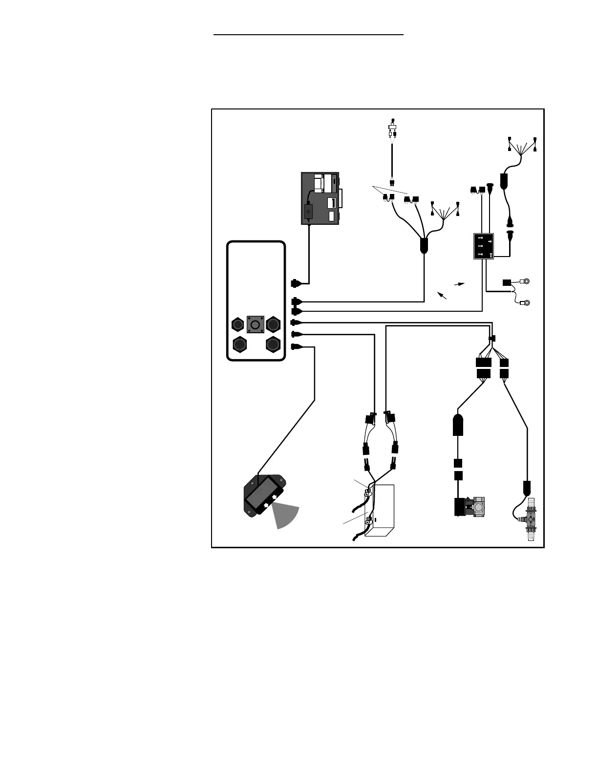
TYPICAL ARC-6000 WIRING DIAGRAM
ARC-6000 CONSOLE
113-0001
Fuse,(10 amp)
Speed Sensor
Console Power Cable
401-0010
MIDWEST TECHNOLOGIES, INC.
M-T 94354
Flow Control Cable
404-0022
Flowmeter Interface Cable
405-0044
Flow Meter
Valve Interface Cable
405-0143
(To Boom Control Switches)
Boom Interface Cable
405-0036
To Implement Status Switch
(optional)
G.S.O. Switch
(optional)
Red
Fuse,(5 amp)
BP-6000 Printer (Optional)
117-0011
NOTE: Boom Status Lines must
be wired to go high (+12 V.dc)
when the Boom Valves are ON.
NOTE: Install Shorting Plug,
if optional switch is
not used.
1
2
3
4
5
Battery Power Cable
45-05037
To boom Interface
1
2
3
MASTER
GSO
OPTIONAL
Boom Switch Box
405-xxxx
Accessory Power
Auxilary Power
Implement
Status
Boom Solenoid Cable
405-xxxx
Ground Speed
(either/or, not both)
Flow Control Valve
Fig. A 1. ARC Flow Control - Wiring Diagram