1-1
98-05012
R3
ARC-6000
T
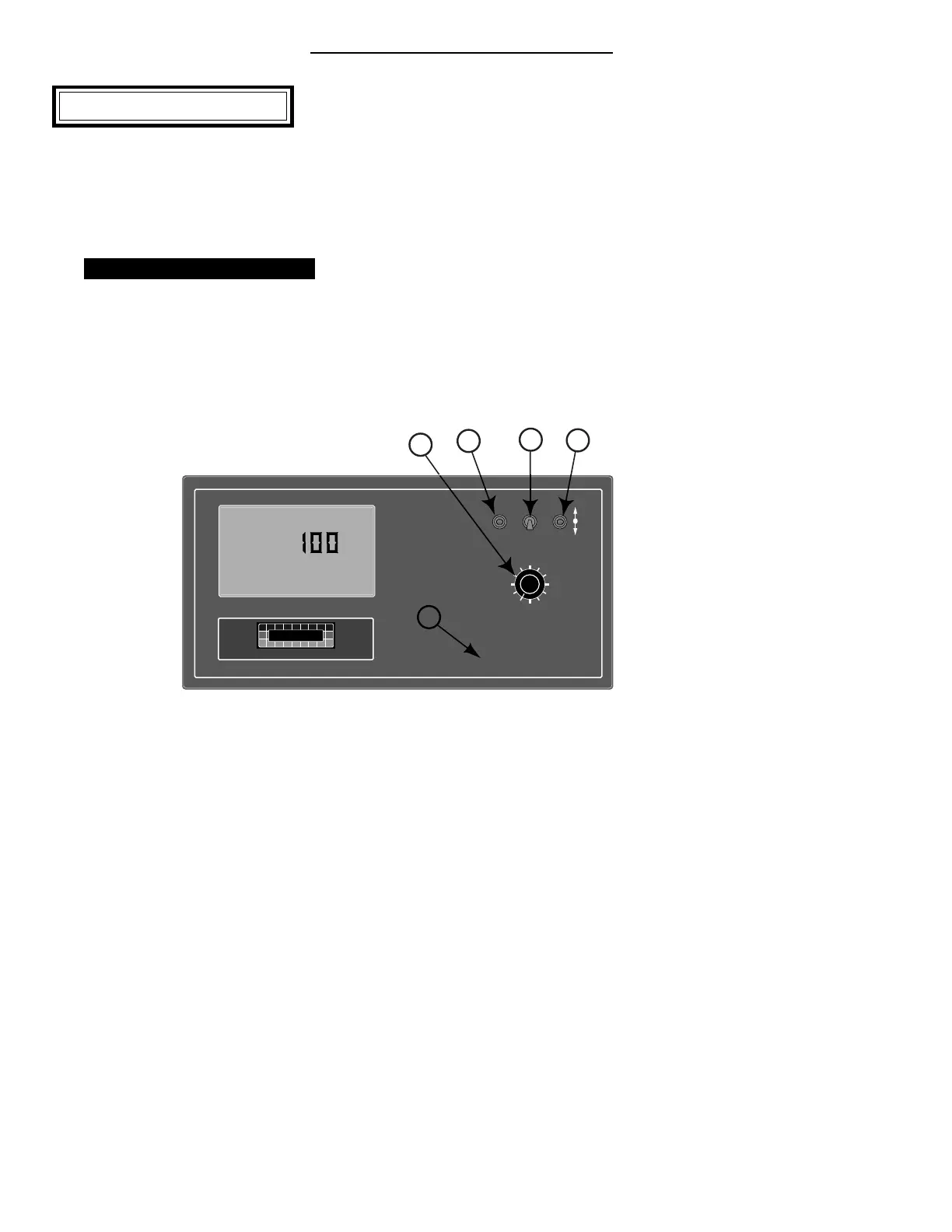
his chapter shows the location of each switch
and indicator found on the ARC control console
and discusses its function in both the Operate
and Setup modes. (Further information can be found
on pages shown in parenthesis.)
Console Switches and Indicators
POWER SWITCH
T
he Power switch (See #1 in Fig. 1-1) controls
the power to the console. Always turn the
Power switch “ OFF” when not in use. This
protects against accidental operation of the control
system and unnecessary current drain on the vehicle
battery.
Don’t
worry about
the console
losing the
set-up
information
with the
power
turned off.
The ARC
Control
Console has
a nonvola-
tile memory
that doesn’t require constant power to hold it’s
information.
MODE SELECTOR SWITCH
The Mode Selector switch (See #2 in Fig. 1-1) is used
to switch between the OPERATE and SETUP modes
of the Control Console. When applying product, this
switch must be in the “ OPERATE” position. The
“ SET-UP” position is used for entering information
into the console. In the SETUP Mode an “ Err”
message appears if a position is selected which can not
be programmed.
%Rate
DISPLAY SELECTOR
Speed
Field Area Impl.Width
Distance
Test
Speed
Prime
Total Applied
Application Rate
OFF SET- UP DEC.
ON OPERATE INC.
Scan
Total Area
Product Vol.
ARC-6000
Automatic
Rate Controller
MID-TECH
¨
MIDWEST TECHNOLOGIES, INC.
123456789
BOOMS
.
-Ac
Flow
RATE
Gal./
3
1
2
4
5
Chapter 1 Switches and Controls
Fig. 1-1. ARC Console -
Switches and Indicators