V5 X VRF 50/60Hz
201608 99
Part 5 - Diagnosis and Troubleshooting
… flowchart continued from previous page
Wires between DC filter board and
inverter module are loose
Ensure the wires are
connected properly
Wires from three-phase bridge rectifier
to reactor, DC filter board and/or AC
filter board are loose
4
Ensure the wires are
connected properly
The power supply is abnormal
Check the power
supply equipment
Voltage between
power output and
neutral terminals on
main PCB are
220±10%V AC
5
Wiring connections
at contactor
terminals is(are)
loose
Ensure the
wires are
connected
properly
Replace three-phase bridge rectifier,
reactor and/or capacitor
Notes:
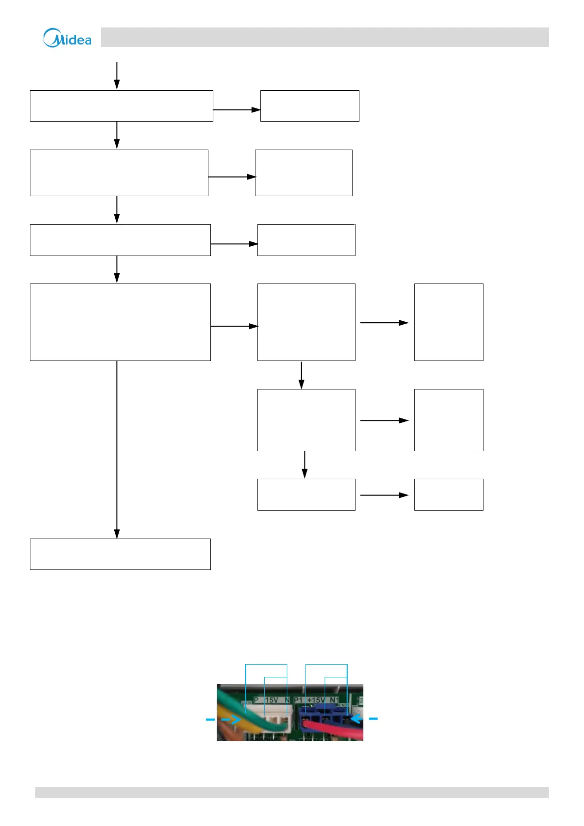
1. Inverter module voltage monitor ports are ports CN36 and CN38 on the main PCB (labeled 22 and 21, respectively, in Figure 5-2.1 in Part 5, 2.2 "Ports").
The normal voltage between the +15V and N pins is 15V DC. Refer to Figure 5-4.19.
2. Inverter module voltage monitor ports are ports CN36 and CN38 on the main PCB (labeled 22 and 21, respectively, in Figure 5-2.1 in Part 5, 2.2 "Ports").
The normal voltage between the P and N pins should be between 300V and 800V. Refer also to Figure 5-4.19.
Figure 5-4.19: Inverter module voltage monitor ports
CN36: Inverter module A
voltage monitor port
CN38: Inverter module B
voltage monitor port
 Loading...