V5 X VRF 50/60Hz
100 201608
Midea V5 X Series Service Manual
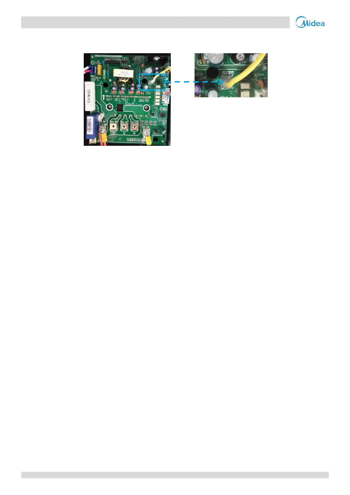
3. Voltage monitor port is port CN5 on the inverter module. Refer to Figure 5-4.20.
Figure 5-4.20: Voltage monitor port (CN5) on inverter module terminals
4. Refer to Figures 5-1.1 to 5-1.4 in Part 5, 1 “Outdoor Unit Electric Control Box Layout” and to the V5 X Engineering Data Book, Part 2, 5 “Wiring Diagrams”.
5. Power output port is port CN54 on the main PCB (labeled 16, in Figure 5-2.1 in Part 5, 2.2 "Ports"). Neutral terminals are terminals CN57-59 on the main
PCB (labeled 17, in Figure 5-2.1 in Part 5, 2.2 "Ports")
 Loading...