SECTION V
SCHEMATICS AND DIAGRAMS
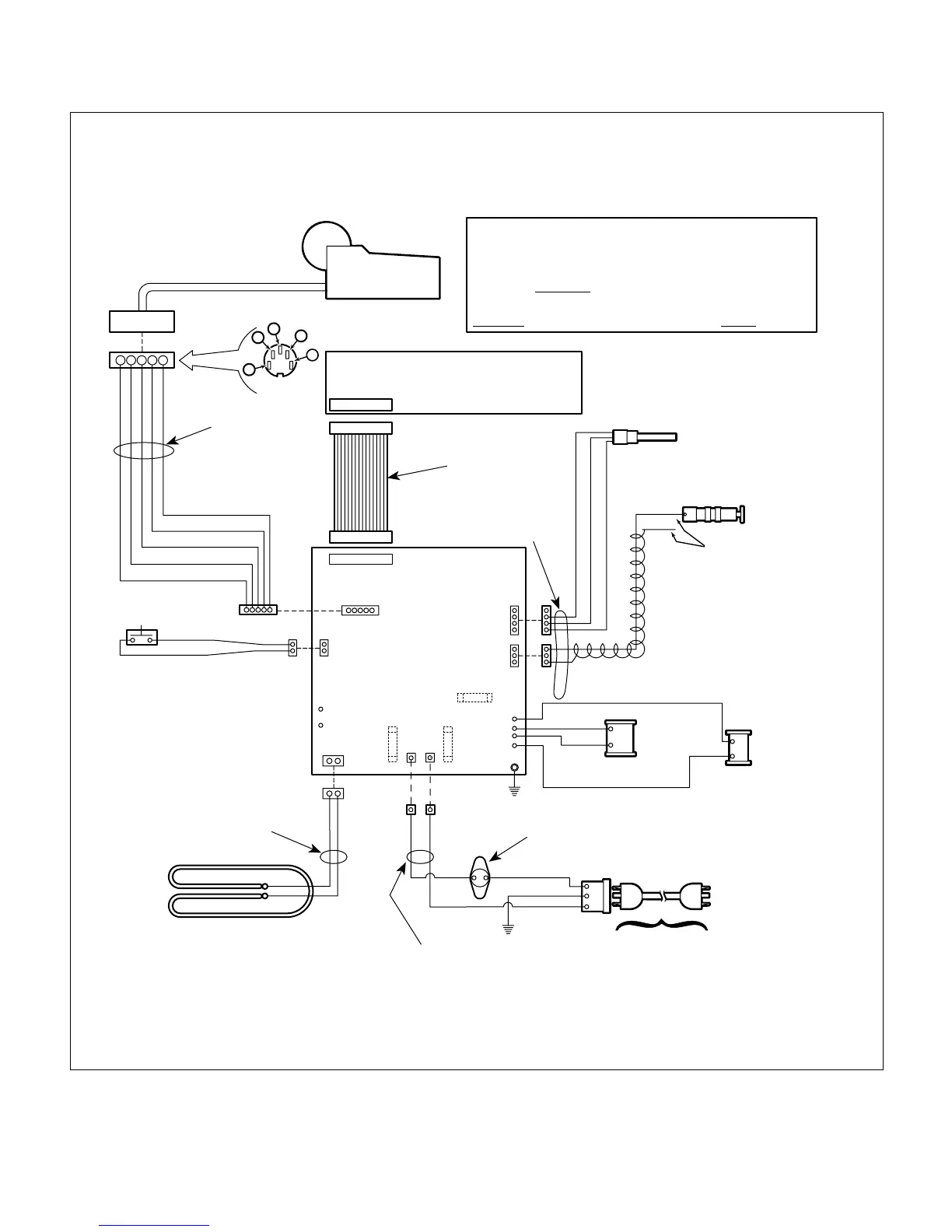
Figure 5-4. (Sheet 1 of 2) M11D Wiring Diagram
(Applies to Units With Serial Numbers GC1000 thru GC1018 and GD1000 Thru GD1015)
© Midmark Corporation 2002 SF-1827 Rev. 5/03 Page 5-9 Printed in U.S.A.
MA246710
Display Panel
PC Board
Ribbon Cable
Connector
Temperature
Probe Assembly
Level
Sensor Assembly
Blue
Door Switch
Yellow
Green
PCB/Heater
Harness
Heating Element
N.O.
Control
PC Panel
PCB/AC/Thermostat
Harness
Black
White
Green/Yellow
Overheat
thermostat
Cordset
A.C. Connector
Receptacle
Fill Solenoid
Vent Solenoid
Black
Black
ORANGE
Red
Black
Chamber Level
Sensor Harness
Black (+5 V.)
Red (V. Out)
White (Ground)
Flex Guard
Tubing
Hot
Neutral
Ground
Black
L
G
N
U.S.A. 015-0640-00
Cont. Europe 015-0688-07
Italian 015-0688-08
Swiss 015-0688-09
United Kingdom 015-0688-10
Australian 015-0688-11
Israeli 015-0688-12
Japanese 015-0363-06
1
2
3
4
5
Printer
Printer
Connector
12345
Orange (Ground)
Green (Ground)
Red (Power)
Blue (Busy)
White (Data)
PCB/Printer
Harness
ORANGE
120V Unit 10.00 to 11.05 ohms
120V Unit 140 ohms
120V Unit 1170 ohms
(*) NOTE:
Some Solenoid Coils may be marked
FWR (Full Wave Rectified).
Use the
Mohms
scale to measure these coils.
If reading is 0.2 Mohms or above, coil is
GOOD
. If OL is displayed, coil is
BAD
(*)