Setup - 8 Midway Amusement Games, LLC
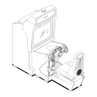
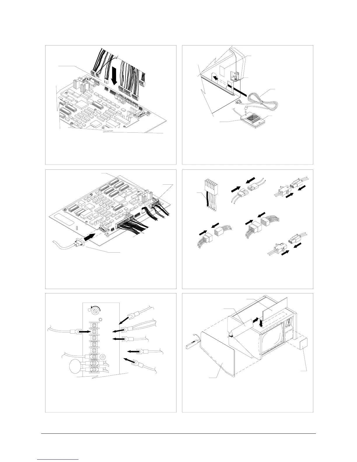
Install conversion VGM electronics.
Orient board assembly with heat sink to front left
of VGM. Point volume control to front of VGM.
Slide CPU Board Assembly into cabinet. Attach
touchscreen controller cable to board.
Attach DC power wires to power supply.
Attach touch controller wires to +12 and GND.
Stow wiring and cables in front of security bar.
Verify power supply connections.
Snugly attach, but do not force wiring harness
connectors into new board assembly. On the
unkeyed black connector, tabs should face in
toward the board assembly.
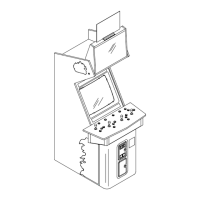
Plug in VGM and turn on power. Calibrate and
test. Remove artwork. Align side decals with top
of cabinet. Apply decals trim to fit. Cut keyhole.
Apply correct sized front decal. Add marquee.
(green/yellow)
FG
Attach 6-pin connector to video board. Orient
yellow/red wire as red one was before. Attach:
fan, speaker, coin, and coin lockout (if applicable)
connectors. Use 9-pin adapter if needed.
Attach touchscreen connector to controller.
Mount controller on bolts or with hook and loop
fastener so LED faces rear or right of VGM.
Attach any ground lugs to mounting bolt. Stow
excess cable between metal walls.
RED &
YELLOW
WIRE
(black)
GND
+5V 12A
+12V 2A
TYPICAL POWER SUPPLY
-5V 1A
MASTER VOLUME
CONTROL
TOUCHSCREEN
CONTROLLER CABLE
VIDEO
FAN
SPEAKER
COIN
ADAPTER
(not used)
CORD
HOOK & LOOP
TOUCHSCREEN
CONTROLLER
BULKHEAD
HOOK & LOOP
1
2
43
5
6
LEFT SIDE
DECAL
FRONT PANEL
DECAL
UNKEYED BLACK
CONNECTOR
H
(black or green)
GND
(orange)
COIN
LOCKOUT
(green from touch controller)
(orange from touch controller)
HEAT SINK
MARQUEE RETAINER
MARQUEE
DECAL
(red)