Touchmaster
®
Conversion Kit Setup - 15
+12V
+5V
(green/yellow)
FG
AC 115V
(not used)
(black)
H
GND
-5V 1A
GND
(orange from touch controller)
(green from touch controller)
(black/green)
47Hz~63Hz
INSIDE CHANGE
190V~260VAC
95V~135VAC
(red)
(orange)
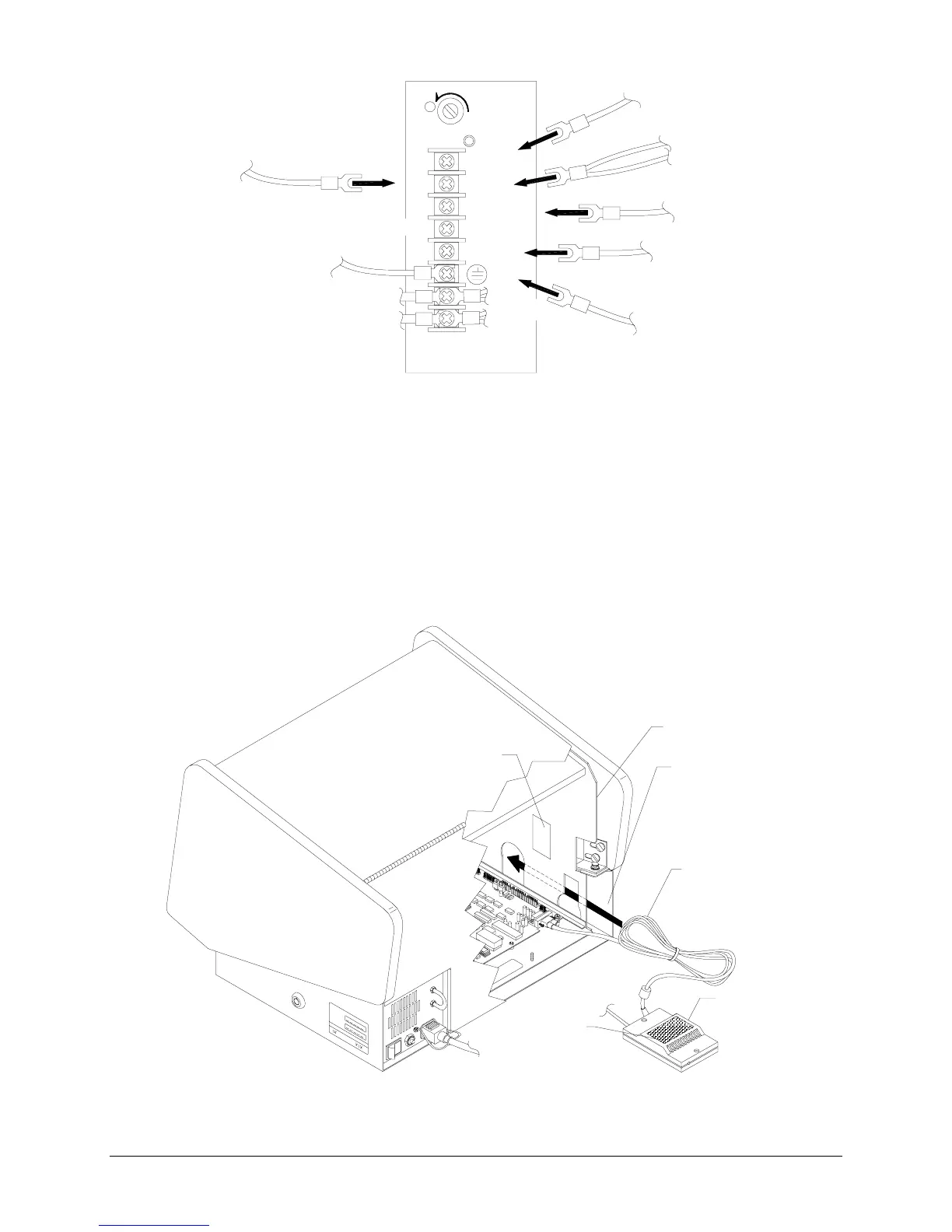
TYPICAL POWER SUPPLY CONNECTIONS
13.
ATTACH
Secure, but do not overtighten, the top six screws on the power supply terminal strip.
14.
CONTROLLER
Attach Touchscreen Controller Connector to the socket on the CPU Board
Assembly. Do not overtighten connector screws.
15.
VIDEO
Attach video connector to monitor board. Orient yellow and red-striped wire in connector
where existing red wire was previously oriented, as noted in electronics removal section of manual.
16.
GROUND WIRE
Reconnect any additional ground wires removed during disassembly.
17.
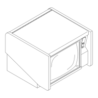
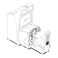
HARNESS ROUTING
Stow wiring in front of the security bar. Ensure that wires are clear of fan. Tie
wrap extra Touchscreen Controller Cable and store in between the cabinet bulkhead and outside
metal wall on the left. Failure to do so may cause difficulty calibrating touchscreen.
HOOK & LOOP
HOOK & LOOP
OUTSIDE
METAL
WALL
BULKHEAD
TOUCHSCREEN
CONTROLLER CORD
TOUCHSCREEN
CONTROLLER
TYPICAL TOUCHSCREEN MOUNTING AND CABLE STOWAGE