Touchmaster
®
Conversion Kit Wiring - 5
LED INDICATOR STATUS CHART
DESIGNATION LOCATION FUNCTION COLOR STATE MEANING
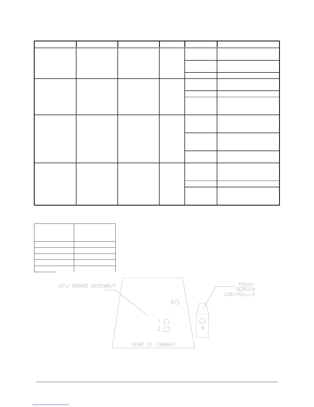
LED 1 CPU BOARD
ASSEMBLY
PROCESSOR
ACTIVITY
RED OFF NO POWER (No DC
power at the CPU)
ON LOCKED UP (Faulty
CPU instructions)
BLINKING NORMAL OPERATION
LED 2 CPU BOARD
ASSEMBLY
RESET
INDICATOR
GREEN OFF NO POWER (CPU not
operating)
ON NORMAL OPERATION
BLINKING ERROR
(Continuous reset at the
CPU)
LED 3 CPU BOARD
ASSEMBLY
INTERFACE
CONDITION
RED OFF NORMAL
(No touch signal from
Controller)
ON LOCKED UP
(Continuous busy at the
interface)
BLINKING TOUCH
DETECTION
LED 4 TOUCHSCREE
N
CONTROLLER
CONTROLLER
CONDITION
GREEN OFF NO POWER (No DC
power at the Controller)
ON NORMAL OPERATION
BLINKING ERROR
(Internal Controller error.
See note for details.)
NOTES FOR LED 4, Internal Controller error.
Number of
flashes every
10 seconds
Reason
1 RAM fault
2 ROM fault
3 A/D fault
4 NOVRAM fault
5 Analog fault
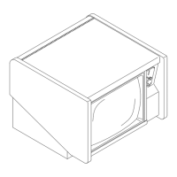
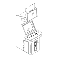
LOCATIONS OF LED 1, 2, 3, and 4 IN CABINET