Setup - 14 Midway Amusement Games, LLC
4.
TOUCHSCREEN
Connect the touchscreen controller connector to the bottom of the new controller.
5.
MOUNTING
Orient the new controller in the same position as the previous controller so that the LED
faces the rear of the cabinet. If the controller is mounted on the rear bracket, the LED should face to
the right of the cabinet. If no controller existed before, install the hook and loop fastener material
included with the kit. Be certain that the controller position will not interfere with other components or
the closed cabinet door.
6.
GROUND WIRE
If there was an existing ground wire, attach it to the threaded stud on the metal
plate. A nut is supplied with the kit hardware just for this purpose.
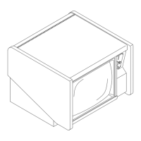
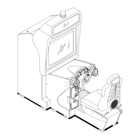
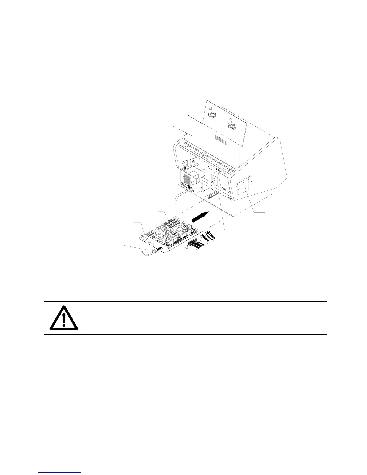
PC BOARD ASSEMBLY
METAL PLATE
SECURITY BAR
REAR DOOR
WIRING HARNESS
THREADED STUD
TOUCHSCREEN
CONTROLLER CABLE
TOUCHSCREEN
CONTROLLER
TYPICAL REAR CABINET VIEW
7.
INSERT VGM ELECTRONICS
The CPU board assembly is mounted on a metal plate. Slide the
plate into the slots at the base of the VGM until it is clear of the cabinet door.
CAUTION: ROUTE CABLES IN FRONT OF THE CABINET SECURITY BAR
. You will
need to lock the cabinet door with the security bar later. Ensure you have clearance by
keeping all cables beneath and in front of the security bar.
8.
FAN
Attach the 2-pin fan connector if you disconnected it previously.
9.
SPEAKER
Attach the 2-pin speaker connector.
10.
COIN
Attach the 15-pin coin mechanism cable connector. If your VGM’s coin mechanism has a 9-
pin connector, use the 9-to-15 pin connector to mate it with the 15-pin connector. Reconnect the coin
lockout connector, if applicable.
11.
POWER
Install the harness to the power supply terminal strip at the following screws:
+5V (red wire)
GND (black wire)
GND (black wire and green wire with yellow stripe)
+12V (orange wire)
FG (green wire with yellow stripe) should already be connected.
The –5V terminal is not used. The AC wires remain connected from the original equipment.
12. Attach touchscreen controller power wires at the GND screw (green) and the +12V screw (orange)