H
Hannah ShawSep 8, 2025
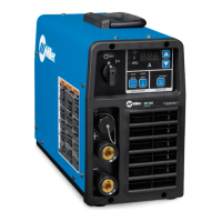
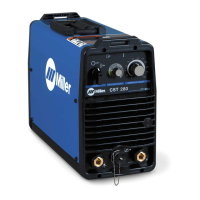
What to do if my Miller CST 280 has no weld output due to voltage loss?
- CChristina EvansSep 8, 2025
If your Miller Welding System has no weld output, it might be due to a voltage loss. Check the Vfb leads to ensure they are properly wired and connected.