OM-258 035 Page 28
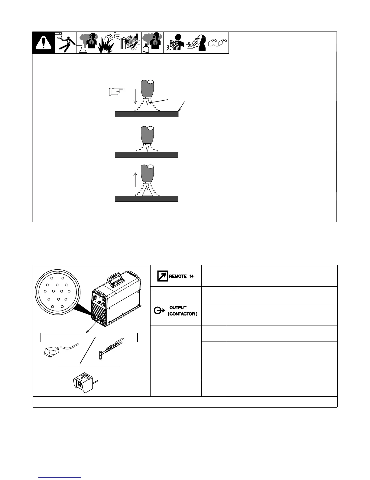
6-4. Lift-Arc™ Start Procedure
Lift-Arc Start
With Lift-Arc selected, start arc
as follows:
1 TIG Electrode
2 Workpiece
Turn gas on. Touch tungsten
electrode to workpiece at weld start
point. Hold electrode to
workpiece for 1-2 seconds, and
slowly lift electrode. Arc is formed
when electrode is lifted.
Normal open-circuit voltage is not
present before tungsten electrode
touches workpiece; only a low
sensing voltage is present between
electrode and workpiece. The
solid-state output contactor does
not energize until after electrode is
touching workpiece. This allows
electrode to touch workpiece
without overheating, sticking, or
getting contaminated.
Application:
Lift-Arc is used for the DCEN
GTAW process when HF Start
method is not permitted, or to
replace the scratch method.
1
1 − 2
Seconds
“Touch”
Do NOT Strike Like A Match!
2
Lift-Arc Start Method
6-5. Remote 14 Receptacle Information
This unit automatically senses when a remote control is connected to the remote 14 receptacle. After connecting a remote control, the unit will
automatically adjust output control to a primary/secondary configuration. In this configuration, the AMPS control on the unit becomes the primary and
sets the maximum amperage output of the unit. The remote control becomes the secondary and provides an amperage range adjustment of 0 to 100%
based on the AMPS control setting.
AJ
B
K
I
C
L
NH
D
M
G
E
F
258 649-A
Socket* Socket Information
15 VOLTS DC
A 15 volts dc (not functional).
B Contact closure to A completes 15 volts dc
contactor control circuit (not functional).
REMOTE
OUTPUT
CONTROL
C Output to remote control; 0 to +10 volts dc.
D Remote control circuit common.
E 0 to +10 volts dc input command signal from
remote control.
GND
K Chassis common.
*The remaining sockets are not used.
6-6. Fan-On-Demand
This unit is equipped with Fan-On-Demand. The fan operates only when necessary to cool internal components. At power down, the fan will operate for
a short period of time while the output indicator light is flashing.
6-7. Rack Mounting
This unit is capable of being rack mounted. See rack Owner’s Manual, OM-221 611.