OM-258 035 Page 30
7-3. Troubleshooting
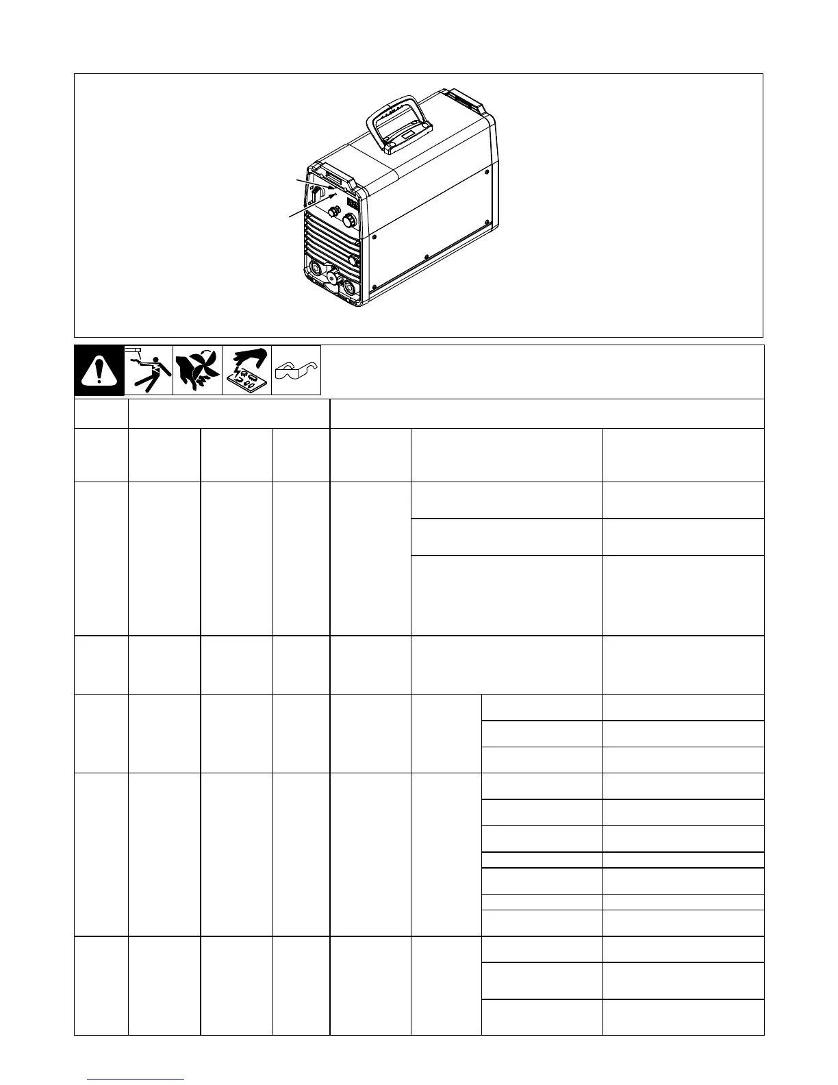
1 Output LED (Blue)
2 High Temperature LED
(Yellow)
258 649-A
1
2
Repeated LED Flashes Indicate
Status
Display
Code
Blue Yellow
Red
(LED1
On
PC13)
Trouble Possible Causes Remedy
None (Prior to
MA050
280G)
None
(Prior to
MA050
280G)
None
No weld output;
unit completely
inoperative.
Line Disconnect open.
Place line disconnect switch in on
position
(see Section 5-9 or 5-10).
Improper input connections.
Check for proper input
connections
(see Section 5-9 or 5-10).
Incorrect input voltage depending on
Voltage Selection Switch position. PTC1
and PTC2 on PC2 overheated due to when
unit was turned on.
Turn off welding power source,
open rear switch cover, and turn
Voltage Selection Switch to correct
input voltage. Allow a 10 minute
cooling down period before turning
welding power source back on
again.
H09
Alternating
Blue And
Yellow (Eff
w/MA050280
G)
Alternating
Blue And
Yellow (Eff
w/MA050
280G)
12
No weld output;
unit completely
inoperative.
Process Select switch is between posi-
tions.
Verify Process Select switch is not
between positions.
H01
Flashes
Continuously
0 7 No weld output. Not ready.
Line voltage too high or
too low.
Line voltage must be ±10%.
Unit is linked incorrectly.
Check line voltage and link
accordingly.
Buss voltage imbalance.
Check DC buss caps and PC2, and
replace if necessary.
H06 6 0 1 No weld output.
Over-current
fault.
No primary lfb.
Check CT1 and wiring for an open
condition.
Faulty output diode(s) D1
or D2.
Check for shorts or opens in wiring.
Faulty boost inductor L3.
Replace boost inductor L3 if
necessary.
Faulty HD1. Replace HD1 if necessary.
Open connection between
HD1 and PC1 or PC13.
Inspect all wiring and
connections.
Faulty PC13. Replace PC13.
Faulty PC2 (239001 or
245857)
Replace PC2.
H04 4 0 8 No weld output.
Over-voltage
latch.
Shorted boost relay CR1.
Check for a shorted relay CR1 or
wiring.
Boost relay CR1 does not
de−energize after ter-
mination of weld.
Check PC13.
Voltage in excess of 100V
from another source ap-
plied across output studs.
Check for external voltage sources.
 Loading...